
Endwinding Vibration Monitoring of Turbogenerators
Abstract
The endwinding region of large turbine generator stator windings is one of the most complex parts of a generator to design, manufacture and assemble. During normal operation, the endwindings are subject to high mechanical forces at twice power frequency due to the currents in the stator bars, as well as mechanical forces transmitted via the core and bearings at rotational speed. During power system transients, the forces in the endwinding can easily be 100 times higher than in normal operation. The design of the endwinding must account for thermally induced axial expansion and contraction as the generator is loaded and unloaded. Due to the presence of high magnetic and electric fields, metallic components to restrain the movement of the stator bars caused by these forces are normally avoided. In this paper off line test results and on line monitoring data from 288 MVA, 21 kV air cooled generator will be described. Offline impact test data led to installation of fibreoptic endwinding vibration sensors. Continuous on line monitoring indicated increase in vibration levels and visual inspection of endwinding confirmed loosening of end winding support structure.
Background
The primary function of a stator endwinding is to allow for the safe electrical connection between bars in series and to other parallels. These connections must be made away from the stator core to prevent insulation failure at the connection points. On higher voltage machines the required creepage distance between the core and the connections can become quite long. Additionally, higher speed machines have long endwindings for geometric reasons, e.g. 2m or longer is not uncommon [1]. The long unsupported lengths of endwinding bars, particularly on high speed machine become susceptible to excessive motion resulting in vibration.
There are two primary forces contributing to endwinding vibration: 1) the electromagnetic force resulting from stator winding conductors carrying the current and 2) the force resulting from rotation of machine at nominal speed. The first force is proportional to the square of stator current [2] and its frequency is two times higher than system frequency, 100 Hz in 50 Hz systems, and 120 Hz in 60 Hz systems. The second force is occurring at system frequency for two pole machines and half of the system frequency for four pole machines.
These forces can be measured in three directions. Considering the end view of stator these are normally specified as radial, tangential (or circumferential), and axial. For the electromagnetic force the directions of most concern are radial and tangential. This is because the force is generated by two parallel current carrying conductors, i.e. the force between the top and bottom bar (radial) and between two adjacent bars (tangential) [2]. This force in the axial direction is typically negligible. The turning speed force is present in the three directions, but typically more significant in the radial and tangential directions.
To accommodate for these forces during operation each bar is often lashed to a support ring made of insulated metal. The hoop strength of the support ring prevents movement in the radial direction. Insulated blocks placed between adjacent bars prevent movement in the circumferential direction. Depending on the length of the endwinding one or more rows of blocking may be present [1].
An additional force in a stator endwinding is due to thermal expansion resulting in growth of the bars in the axial direction. Endwinding support design is a balance between stiffness to prevent movement in the radial and tangential directions from normal operating forces and flexibility to allow for growth due to thermal expansion. This need for opposite characteristics of stiffness and flexibility is a challenge when designing endwinding support systems [3].
Endwinding vibration from excessive motion in the stator endwinding structure is most likely to occur in form wound two- and four-pole machines since the endwindings are long. The windings pivot at the slot exit because they are held tight in the slot which creates a cantilever effect in the endwinding area. Proper endwinding support is required to prevent movement from this effect where the vibration forces can lead to fatigue cracking of the insulation and even the conductors at the core end or at the connections. Stator winding deterioration may be the result of poor design or aging of end-winding support components. Both can be contributing factors to resonant conditions which is a situation when the endwinding natural frequency is similar to the frequency of electromagnetic forces (twice the system frequency). In the case of resonant conditions occurring in operation, normally occurring vibration will be significantly amplified. Frequent stops, system disturbances and aging, can also affect the condition of endwinding and result in a change of winding natural frequency.
Different methods can be used to assess the condition of the endwinding, such as impact (bump) testing and visual inspection, both requiring partial disassembly of machine. The purpose of the bump test is to find natural frequency of the stator winding and identify the loosest components in the endwinding. These tests are periodic, and cannot provide timely information about how fast the insulation is degrading. With this in mind and given that there is not always access to the stator windings for inspection, online monitoring of stator windings has become the best and most modern way of detecting changes to the endwinding support structure.
Electromechanical vibration monitoring is well developed and it is possible to monitor machine condition with vibration data collected on the shaft and bearing housings. This is most effective for identifying issues related to the rotor dynamics of the machine (unbalance, misalignment, bearing looseness, etc) with metallic piezoelectric accelerometers and non-contact probes measuring eddy currents proportional to shaft displacement. These same methods cannot be applied on stator endwindings in particular near the coil ends where the vibration amplitudes are the highest because metallic materials in close proximity to high currents will heat up due to losses induced by magnetic fields. Metallic accelerometers may compromise the electrical clearances of the endwinding to ground and can result in partial discharge. With the development of non-metallic fiber optic accelerometers though, it is possible to monitor the movement of endwinding coil ends.
With the continuing advancement of fiber optic technology and our increasing knowledge of stator endwinding structural and vibratory behavior other important considerations are required for effective online monitoring of stator endwinding vibration.
Case Study – 288MVA, 21kV, 2-pole Air Cooled generator
In a driving point impact test the force hammer and the accelerometer are at the same measurement location and the result is a measured response at the excitation point known as a frequency response function (FRF). This transfer function is expressed in the frequency domain with amplitude and phase. The phase will be between 0 and 180 degrees or 180 and 360 degrees and be ~90 degrees at a natural frequency. Two observations are required to identify a natural frequency. As a driving frequency approaches an undamped natural frequency, 1) the magnitude approaches a maximum and; 2) a phase shift crosses through 90° [4]. To identify natural frequencies these observations can be determined with impact testing.
The critical bands for a turbine generator are around rotational speed frequency and twice line frequency. Therefore, applied forces in the endwinding structure of a 2-pole, 60 Hz generator are at rotor rotational frequency, 60 Hz and at alternating load current electromagnetic forces, 120Hz. The concept of critical band refers to the risk of vibration amplification when the structural natural frequencies are close to the forcing frequencies. This condition is resonance. In service, the natural frequencies may drift in the bands due to temperature [3], aging and other variable factors. Thus, an acceptance band should be defined with these factors in mind. The acceptance criteria are based on the magnitude of the acceleration over force through the critical excitation bands of, for example -10% and +20% of the fundamental excitation frequencies (60 and 120Hz). If the response is greater than 0.44 (m/s2)/N the endwinding may be loose [1].
In June 2012 offline impact testing was performed after a modification to the endwinding support structure on the exciter end of a 288MVA, 21kV, 2-pole air cooled generator. The results showed no critical natural frequencies near the critical bands. The FRF results of the 11:00 top and bottom jumper connections are shown in Figure 1. The 5 lines represent all 3 directions on the top jumper and in the radial and axial directions on the bottom jumper. The tangential direction on the bottom jumper was not accessible.

Figure 1 – 2012 Offline Impact Test at 11:00 Jumper Connections
Fiber optic Endwinding Vibration Accelerometers (EVAs) were installed to monitor the vibration of the endwinding support structure and windings during operation. After 2 years of operation, there was a significant increase in vibration amplitudes resulting in overall displacement levels as high as 350μm p-p on the sensor installed near the 11:00 jumper connections, see Figure 2.
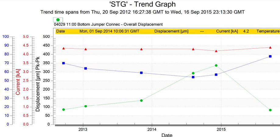
Figure 2 – Online Endwinding Vibration Trend of 11:00 Bottom Jumper Connection
The dominant vibration peak was at 120Hz and the highest amplitude recorded was 315μm p-p, see Figure 3. Although there is no consensus regarding endwinding vibration acceptance limits, any displacement higher than 250μm p-p is considered concerning [1, 2]. This amplitude is particularly concerning because it increased from 66μm p-p measured on September 2012.
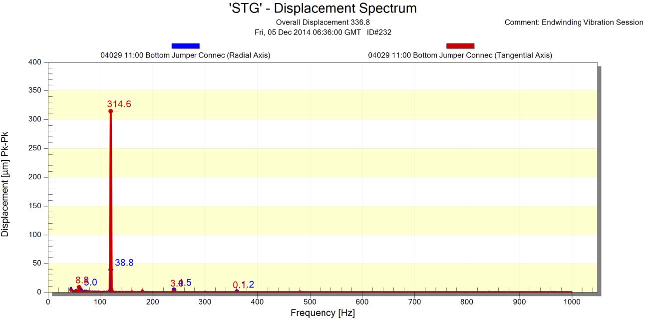
Figure 3 – Displacement Spectrum of 11:00 Bottom Jumper Connection
The vibratory condition prompted a visual inspection of the endwinding support structure during the next outage that revealed loose support blocking and dusting between the jumper connection and radial support ring in 5 locations, see Figure 4.
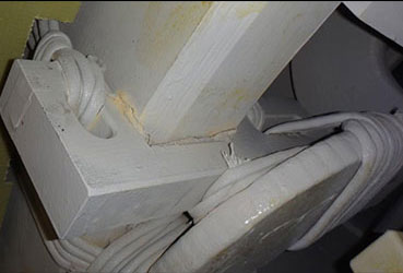
Figure 4 – Loose blocking near 11:00 Jumper Connection
The original outage plan did not include inspection of this generator meaning the loose blocking would not have been identified without the endwinding vibration monitoring system. In addition to the visual inspection, an offline impact test showed that the online vibration levels increased due to resonance near 120Hz, see Figure 5. The significant reduction in stiffness from the loose support block reduced and separated the natural frequencies into a resonance condition during operation.
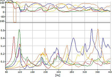
Figure 5 – 2014 Offline Impact Test at 11:00 Jumper Connections
The 2014 outage plan did not allow for enough time for a permanent repair so the endwinding vibration levels were monitored closely until the loose blocking could be addressed in 2015. Offline impact testing, Figure 6 and online vibration data, Figure 2 show that after the blocks were replaced the condition was similar to that of 2012.
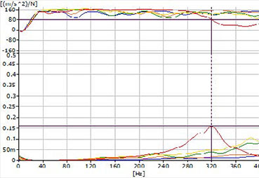
Figure 6 – 2015 Offline Impact Test at 11:00 Jumper Connections
Conclusions
Advancements in the design of sensors and data processing enabled more effective monitoring of the stator endwinding condition. This is even more important now, when machines are designed less conservatively than before, and operated with more cycling leading to an increased number of problems. The case study presented shows the importance of using offline impact testing to better understand the online vibratory response. Once excessive vibration in the stator endwinding and support structure has been detected the following remedies should be considered [1]:
1. Complete endwinding support replacement
2. Reinstall blocking and lashing material
3. Installation of additional blocking and bracing
The above should be done in conjunction with impact testing to ensure any changes made to the support system does not have a negative effect on the resulting vibration amplitudes during operation. Continuing to monitor the online stator endwinding vibration will indicate if the results of any structural changes are positive and when additional remedies are required from aging of the support structure and/or excessive forces from high current faults.
References
1. G.C. Stone, E.A. Boulter, I. Culbert, et al. Electrical Insulation for Rotating Machines, 2nd ed. Hoboken NJ: Wiley, 2014.
2. H.O. Ponce, B. Gott, G. Stone, Generator Stator Endwinding Vibration Guide: Tutorial, EPRI, 2011. Project Evaluation No 6382.
3. M. Sasic, H. Jiang, G.C. Stone. Requirements for Fiber Optic Sensors for Stator Endwinding Vibration Monitoring, in Proc. IEEE-CMD, 2012, pp. 118-121.
4. Inman, D.J. Engineering Vibration. 2nd Ed. Upper Saddle River, NJ: Prentice Hall, 2001.