
Although the phenomenon of voltages and currents on motor and generator shafts has been known for the last 100 years, there has been an increase in occurrences and intensity of shaft current damage as machines become larger, operate at higher speeds, and more magnetic-based non-destructive inspection tools are used. This problem may affect all types of rotating machines (electrical and non-electrical, such as compressors and pumps) but it is most frequently observed on 2-pole and 4-pole turbine generators.
Cause of Shaft Voltages and Current
During the normal operation of electrical machines, AC and DC voltages can be induced in the shaft, or created by the rotating elements of the turbine, connected to the same shaft. If voltages are high enough, shaft cur-rents can reach levels capable of causing bearing failures. The main sources of shaft voltages are:
- Asymmetry of magnetic fields (incomplete cancellation of three phase magnetic fields) caused by design, manufacturing, or by stator winding, rotor winding or core faults.
- Flux generated by magnetized turbine and generator parts in the vicinity of the shaft.
- Shaft off center position.
- Electrostatic effects caused by charged steam or lubricants.
Impacts of Shaft Voltages and Current
In addition to pitting (mechanical damage resulting from arcing between shaft and bearing) or EDM (electro-discharge machining), shaft currents may also alter the chemical properties of lubricating oil. Although the shaft is less sensitive to sparking effects, compared to the bearing surface, a more serious effect of bearing currents on the shaft is the mechanical wear produced by the buildup of metallic debris.
Without effective shaft grounding, bearings and oil films are the only insulation between the shaft and the grounded parts and as shaft currents are not confined, they cannot be controlled. The build-up of voltage on the shaft and the resulting currents may damage bearings and could result in catastrophic rotating machine failure.
Avoiding Bearing Failures Through Shaft Monitoring
To control and keep shaft voltages low, one or both of the generator shaft bearings are insulated and the shaft is grounded using one or more closely spaced grounding devices, usually carbon, silver or copper brush, or copper braid.
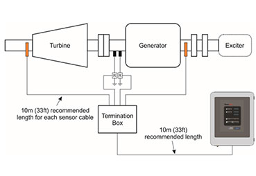
The sensors utilized to provide signals for Shaft Voltage Monitoring consist of insulated shaft riding brushes for shaft voltage sensing and shunts installed on the shaft grounding brushes, for shaft current sensing. Different methods have been proposed to measure the effective-ness of the shaft ground brushes that are used to prevent excessive shaft voltage and currents. IEEE 112, Standard Test Procedure for Polyphase Induction Motors and Generators, provides a brief description of shaft current and voltage measurement methods, and a comparison of different techniques is given in IEEE 115, while IEEE 1129 gives a short summary of causes and instrumentation used. There is no standardized approach in the selection of sensors, their location or methods used for data collection. The most frequent lay-out is shown in Figure 1.
Figure 1: Typical shaft monitoring configuration on a Turbine Generator
To overcome problems associated with periodic data collection and the use of portable instruments (non-consistent surface contact between shaft and a portable brush, and the inability of an ordinary digital voltmeter to accurately measure non-sinusoidal voltage shapes), Iris Power has developed a continuous Shaft Monitor.
Iris can provide two versions of the instrument, SMTracII as a single technology Shaft Monitor, or it can be delivered as a part of a multi-technology GuardII, where multiple modules (Shaft Monitoring, Flux, End winding Vibration or Partial Discharge) can be used.
Shaft Current and Voltage Monitoring Principles
Shaft current and voltage signals are fed to an active termination box and then to a monitor to facilitate continuous monitoring and pro-cessing of the shaft grounding current and the shaft voltage. These continuously monitored signals are the keys to machine condition determination and can provide an early warning of developing unit problems.
The principal function of the instrument is to warn users about the following situations:
- Poor performance of grounding brush
- Presence of additional grounds on the shaft
- Presence of high voltage on the shaft
In addition, the instrument will automatically collect and store a number of measurements in internal memory. The SMView software provides FFT analysis of the results and trending of data at different fixed and user selected frequencies. Modbus protocol can be used to communicate all measured and calculated values to a remote PC.
The installation of the Monitor can be performed without unit shutdown, but connection to the grounding brush might require the shut-down, depending on the type of brush installed.