
Since they were first introduced over 10 years ago for military applications, it has been known that the voltage impulses from voltage source, pulse width modulated (VS‐PWM) variable speed drives may lead to more rapid deterioration of stator winding insulation system in windings rated 3.3 kV and above. The voltage impulses are created by the rapid switching of the transistors within the drive. The reasons for an increase in the risk of rapid insulation deterioration due to these impulses include:
- More and bigger PD within internal groundwall insulation voids due to higher peak voltages from the drive switching.
- The high frequency content of the drive voltage impulses causes high currents to flow in the stress relief coatings which may lead to overheating and high PD from degraded coatings.
Thus, it is not surprising that many end-users who own such variable speed drives will often want to install an on‐line partial discharge monitoring system. While the LCI, current source inverter and cyclo-converter types of drives do not cause a problem for on‐line PD monitoring, the VS‐PWM drives do. The most popular drive for medium and high voltage motors is now the VS‐PWM drive.
The main issue with monitoring VS‐PWM drives is the short rise time voltage impulses that are inherently produced by the transistor switches within the drive. The voltage switching impulses can have rise times as short as 500 ns, with magnitudes of 2000 V or so. The short rise time creates frequencies up to almost 1 MHz. If the PD sensor is a capacitor – the capacitor will have a very low impedance to 1 MHz, especially if the capacitor is 1000 pF or more (at 1 MHz, the impedance of a 1000 pF sensor is only a few hundred ohms). The result is that a significant portion of the switching impulses are conducted through the capacitor and applied to the test instrumentation. The resulting noise from drive switching can be hundreds to thousands of times the magnitude of the stator winding PD, making even the most knowledgeable expert incapable of extracting the PD from the switching noise, especially if the PD system works in the 10 MHz or lower frequency range.
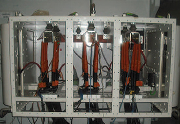
Iris Power was first approached about 10 years ago to install an on‐line PD monitoring system on 7.2 kV motors fed from a VS‐PWM drive. Rather than scale up the existing PDAlert product for inverter drives from 1000V to 7200V, we instead modified the existing 80 pF couplers and the TGA‐B. About 2 years later, the prototype system was installed in the Middle East. The standard 80 pF capacitive couplers were used as the PD sensors (Figure 1). With a 50 ohm load, the lower cut-off frequency is 40 MHz, which partly suppresses the drive switching noise. However, additional filtering with a customizable, multi‐pole
filter is often needed on each capacitive coupler.
Figure 1: Photo of 80 pF capacitive couplers installed on the motor terminal box of a variable speed drive motor. The couplers (circled in red) are partly concealed behind the power cables.
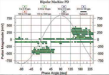
A change was also needed for the TGA‐B instrument. All conventional PD instruments display the PD with respect to the power frequency AC cycle (a pulse phase analysis plot, sometimes known as a phase‐resolved PD plot—see Figure 2).
Figure 2: Example of a PD plot from an operating 7.2 kV, 45MW motor fed by a VS‐PWM variable speed drive.
In the past the TGA‐B was expecting either 50 Hz or 60 Hz power frequency. If the frequency was neither of these, then the instrument would not “synchronize”. For variable speed drive applications, the TGA‐B had to be modified to work with a range of “fundamental” frequencies. After the installation of the prototype in 2007, we discovered that the instrument still could not synchronize to the fundamental frequency.
The reasons were complex. Partly it was due to the reduced fundamental frequency voltage that was measured on the output of the 80 pF PD coupler when the fundamental frequency was well below 50 Hz. There were also problems establishing the voltage zero crossing when the fundamental frequency was “contaminated” with all the switching impulses. In addition, if the speed was such that the plant power frequency (50 or 60 Hz) was close to the fundamental frequency, a low frequency modulation could result that confused the synchronization process. The solution was a separate capacitive voltage divider that emphasized the fundamental frequency, rather than the higher frequency switching impulses.
The result was the first on‐line partial discharge monitoring system in the world that successfully measured the stator winding partial discharge fed by a medium voltage VS‐PWM drive. Example PD data is shown in Figure 2. The system has been operating since 2007, and other systems have been supplied to multiple end users in the Middle East, as well as end users in Asia and North America.
References
M. Stranges, G.C. Stone, D. Bogh, “Voltage Endurance Testing of Stator Insulation Systems for Inverter Fed Machines”, IEEE Industry Applications Magazine, Nov 2009, pp 12‐18.
G.C. Stone, I. Culbert, S.R. Campbell, “Progress in On‐Line Measurement of PD in Motors Fed by Voltage Source PWM Drives”, IEEE Electrical Insulation Conference, Philadelphia, June 2014, pp 172‐175.