
SUMMARY
On-line partial discharge (PD) testing has been used for decades to help maintenance personnel detect stator winding insulation problems in motors and generators. Specifically, the test can find loose, overheated, delaminated and contaminated windings, well before these problems lead to failure. As a result, on-line PD testing has become an important tool for planning machine maintenance. With the advent of electrical noise separation technology developed in the 1970s and 1980s, reliable on-line PD testing and basic interpretation was made possible for plant engineering staff with moderate training. The result has been the widespread application of the so-called PDA and TGA tests on machines throughout the world. Worldwide, more than 15,000 machines now use these technologies.
Widespread application of these test methods has enabled the collection, over more than two decades, of a database with, currently, over 400,000 test results. The results of a statistical analysis of the PD results in this database show that voltage class, machine cooling method, and type of partial discharge sensor are all critical to correctly interpreting test results. Critical values of PD, based on Qm (maximum PD magnitude recorded with a repetition rate of 10 pulses per second), which indicate significant risk of severe winding problems, have been derived for different types of air-cooled and hydrogen-cooled machines. These PD severity levels have been benchmarked against actual stator winding insulation condition obtained from visual inspection and other tests. Thus comparison of test results to the database allows an approximate assessment of the stator winding insulation condition, without having to wait several years for a trend to establish itself. A further advantage of using a statistical approach is that trending requires that machine operating conditions be stable, within limits defined in IEEE 1434 and IEC 60034-27-2 standards, from one measurement to the next. Such a requirement may not always be possible to meet.
KEYWORDS
Partial discharge, electrical insulation, stator winding, condition assessment.
I. INTRODUCTION
Partial discharges can be both a cause and/or a symptom of many types of stator winding insulation system deterioration mechanisms in motors and generators rated 3300 V and above. Thus it is not surprising that the on-line measurement of partial discharges has been used to assess the need for maintenance in stator windings since 1951 [1]. More particularly, on-line PD measurement has been able to determine if the electrical insulation is deteriorating due to loose coils in the slots resulting in insulation abrasion; thermal deterioration or load cycling leading to insulation delamination; and electrical tracking caused by partly conductive contamination of the endwindings [1-7]. On-line PD testing is also able to determine if manufacturing or installation problems, such as poor impregnation with epoxy, or coils being too close together in the endwinding, are severe enough to shorten the winding life.
Many methods are available to measure the PD activity in operating machines. The electrical techniques all rely on monitoring the current or voltage pulse that is created whenever a partial discharge occurs. The earliest methods measured the PD pulse currents by means of a high frequency current transformer at the neutral point [1, 2]. Shortly thereafter, high voltage capacitors connected to the phase terminals were used to detect the PD pulses [3-5]. Capacitor sizes ranged from 80 pF to over 1000 pF. More recently, RF antennae are also used to detect PD in operating machines [6, 7]. A good overview of all the different means for detecting PD in machines is presented in IEEE 1434 [8]. This document also provides the framework to enable reliable on-line PD measurements to be made, as does IEC 60034-27-2 [9].
A particular challenge with PD measurements performed in normal motor or generator operation is that electrical interference (noise) often is present [8, 9, 10]. Noise sources include corona from the power system, slip ring/commutator sparking, sparking from poor electrical connections, power tool operation, and electrostatic precipitator discharging. This noise obscures the PD pulses, and may cause the unwary technician to assume that a stator winding has high levels of PD, when in fact the high levels are caused by the noise. The consequence is that a good winding is incorrectly assessed as being defective – that is a false alarm is given that a winding is bad, when it is not. Such false alarms reduce the credibility of on-line PD tests, and even today, many feel on-line PD testing is more art than science and best left to specialists.
Beginning 25 years ago, the Canadian utility industry sponsored research to develop an objective on-line PD test for machines that could be performed and interpreted by plant staff with only a few days training. The tests that were developed, now known generically as the PDA test (for hydrogenerators) and TGA test (for turbine generators and motors) emphasized separating PD pulses from electrical noise pulses. The noise separation methods depend on comparing the time of pulse arrival between a pair of capacitive couplers and/or analyzing the shape of individual pulses [4, 6]. To maximize the signal-to-noise ratio, and thus also to reduce the risk of false indications, the sensors detect the PD at frequencies 40 MHz and higher [8]. The resulting test methods achieved their goal and have enabled utilities to assess the winding condition with their own staff. As a result, it is estimated that over 50% of all utility generators rated 20 MW or more in the USA and Canada have now been equipped with the required sensors. Around the world, over 15,000 machines have the required sensors permanently installed.
With the widespread application of the same on-line test methods, a tremendous number of test results have been accumulated in a single database. To the end of 2015, over 400,000 test results have accumulated over the past 20 years using portable test instruments, and simple statistical analysis has been applied to the database in order to extract information that can help test users to better interpret PD results. This paper updates a previous contribution from 2002 [11] that introduced this concept. The best means to determine if a winding is significantly deteriorated remains monitoring the trend in PD activity over time. Unfortunately, the PD magnitudes are not only affected by the degree of insulation deterioration, but the machine operating voltage, coolant gas pressure, etc, may also affect results. With the availability of on-line PD monitoring systems that continuously measure the PD on a motor or generator, while simultaneously acquiring machine operating data, a better appreciation of the effect of operating conditions on PD activity has been obtained. Thus this paper also presents the ranges in operating condition that enable the measurement of valid trends of PD activity.
2. PD DATABASE
2.1 Data Presentation
All the data presented here is obtained using either 80 pF capacitive couplers (installed within the stator winding or on the machine terminals) or stator slot couplers (SSCs), which are antennae installed under the wedges in stator slots containing phase end bars [4, 6]. As with most PD measurement systems, the number, magnitude and phase position with respect to the 50/60 Hz ac cycle are recorded, once PD pulses are separated from the noise pulses. The pulse magnitude is measured in the absolute units of millivolts, rather than picoCoulombs, due to the difficulty in calibrating into pC caused by the inductive-capacitive nature of a complete stator winding [8].
Two types of plots are generated for each partial discharge test. The first type of plot is two-dimensional (2-D), where the number of partial discharges per second versus PD magnitude is displayed. The greater the number of pulses per second, the more widespread is the deterioration in the winding. The higher the PD magnitude, the more severe is the deterioration. An example is shown in Figure 1. The second type of plot (Figure 2) is a three-dimensional phase resolved PD (PRPD) plot, where the PD magnitude (vertical scale) and PD pulse repetition rate (colour coded to proportional to pulse density) versus the ac phase angle (horizontal scale) are displayed. Experience has indicated that such pulse phase analysis can be used to identify if multiple deterioration mechanisms are occurring, and the mechanisms responsible.
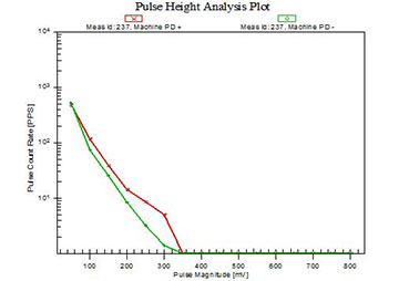
Figure 1: 2-D plot showing the number of partial discharges per second versus PD magnitude.
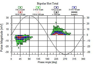
Figure 2: 3-D phase resolved PD plot showing the PD magnitude (vertical scale) and PD pulse repetition rate (colour coded to proportional to pulse density) versus the ac phase angle (horizontal scale).
The 2-D and 3-D plots are unwieldy for making comparisons amongst the machines. The PDA or TGA summarizes each plot with two quantities: the peak PD magnitude (Qm) and the total PD activity (NQN). The Qm is defined to be the magnitude corresponding to a PD repetition rate of 10 pulses per second [9]. Qm relates to how severe the deterioration is in the worst spot of the winding, while the NQN is proportional to the total amount of deterioration and is similar to the power factor tip-up. Since the Qm scalar quantity is more indicative of how close the winding is to failure, the peak magnitude (Qm) will be used throughout this paper for comparisons.
It has been noted that Qm is a reasonable predictor of winding insulation condition [11]. That is, a high Qm measured in a winding compared to a lower Qm in another winding, usually implies that the former winding is more deteriorated. Initially, this was a surprise since the mV readings were not calibrated for winding load. We now believe that the Qm readings reported here, that are measured at frequencies above 40 MHz, may be somewhat absolute because the pulses are measured as traveling waves, and all oscillations after the first peak in a single PD event are disregarded. Since the surge impedance of a coil in a slot is roughly the same for all sizes and types of machines, the very wide band measurement of the first peak in a PD pulse does not ‘see’ the entire capacitive and inductive load of the stator winding, thus leaving the measurement free of the effects of LC oscillations and reflections.
2.2 Database to the End of 2013
After the accumulation of all available test data through 2013 with over 400,000 records from tests using portable instruments only, a database was carefully compiled using the following selection criteria:
- only on-line tests obtained during normal operation
- only one test result per sensor
- the most recent test at Full Load and Hot stator winding temperature (FLH)
- any test with questionable results was discarded
Once these criteria were applied, about 18,000 statistically independent test results from over 5,000 machines were analyzed.
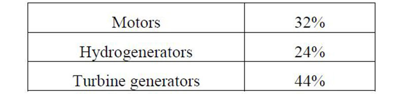
Table I shows the breakdown of the results that were retained once non-FLH and repeat tests were discarded.
Table I: Number of FLH Tests by Machine Type
2.3 Statistical Analysis
The database was analyzed to determine the effect on Qm of several different factors, including:
- Sensor installation
- Voltage class
- Hydrogen pressure
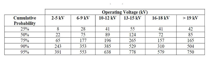
The range in Qm from all the tests for the particular operating voltage was established for each set of the above factors. A sample of the statistical distribution is shown in Table I. The percentage values displayed in the left hand column in Tables II through V, represent the cumulative probability. For example, for 13-15 kV stators in turbine generators or motors, 25% of tests had a Qm below 55 mV, 50% (the median) had a Qm below 124 mV, 75% were below 265 mV and 90% of tests yielded a Qm below 529 mV. Thus if a Qm of 500 mV is obtained on a 13.8 kV generator, then it is likely that this stator will be deteriorated, since it has PD magnitudes higher than 90% of similar machines. In fact, in over two hundred cases where a machine was visually examined after registering a PD level >90% of similar machines, significant stator winding insulation deterioration was observed [12].
Table II: Distribution of Qm (mV) for Air-Cooled Machines, 80 pF Sensors on the Terminals (TGA)
A PDA installation in a hydrogenerator uses the same 80 pF sensors and these are typically installed within one metre of the junction between the incoming phase bus and the first coil/bar in the circuit. A sensor at this location will be extremely sensitive to any pulses originating within the coil/bar since the magnitude of the pulse will be amplified when it reaches the impedance mismatch between the bus and the coil/bar. Thus, it may be reasonable to assume the PD magnitudes obtained with couplers at this location will be higher than when the couplers are located outside the machine housing typical of directional (TGA) installations. However, when comparing the TGA results, Table II, to the PDA results, Table III, though there are some minor variances, there is little significant difference between the statistical summaries for windings rated less than 19 kV. Thus, it is safe to say that for a 13.8 kV winding, regardless of installation type, the PD levels should be less than ~250 mV and those machines with PD higher than 500 mV need further investigation.
Table III: Distribution of Qm (mV) for Air-Cooled Machines, 80 pF Sensors Installed within the Machine Housing (PDA)
Partial discharge is a gas discharge process, thus, it is extremely dependent, not only on the geometry of the gas gap, but also the gaseous medium. Thus, PD magnitudes from air-cooled machines are typically higher than machines cooled with hydrogen at elevated pressure. Therefore, it is not advisable to compare the results from machines using different gas mediums. Most hydrogenerators (PDA installations) are air-cooled, thus all of the tests for gas-cooled machines with capacitors were obtained using a TGA instrument and sensors at the machine terminals. Most of the hydrogen-cooled machines have high rated loads and may suffer from problems such as core iron arcing which may cause difficulties in separating the high frequency noise associated with this phenomenon from that of PD. Partial discharge or noise activity at the machine terminals, outside the hydrogen environment, can make stator winding insulation condition difficult to interpret. This difficulty was the principal reason for the development of stator slot couplers (SSC) that have been discussed at length in other publications [6]. Results obtained with these types of sensors on hydrogen-cooled machines will be discussed later in this contribution.
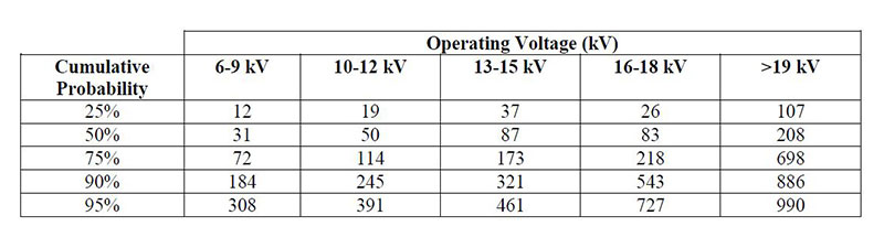
Comparing Table IV to Table I shows that the Qm values for gas-cooled machines are generally lower than for the air-cooled machines for the same nominal voltage rating. This is especially observable at higher pressures, where 75% of the tests for all operating voltages operated above 31 psig are below 110 mV and 90% generally below ~250 mV, less than half of that observed on the air-cooled machines. At the lower operating pressures, the PD levels are generally much higher, with a few machines having extremely high PD of Qm levels >600 mV, which would require more tests and investigation.
Table IV: Distribution of Qm (mV) for Hydrogen-Cooled Machines, 80 pF Sensors on the Terminals (TGA)
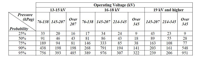
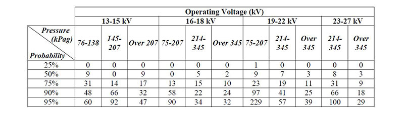
Table V illustrates the similar statistical distribution for hydrogen-cooled turbogenerators where SSCs are installed. Since these machines are operating in a hydrogen environment, the overall slot PD is quite low. In particular, the PD magnitude at the 90% level is significantly lower for hydrogen-cooled machines than for their air-cooled counterparts. It should be observed that though the majority of the machines have slot Qm values less than ~30 mV, there are a few with levels higher than 60-200 mV. These machines should be subjected to further tests and inspections.
Table V: Distribution of Qm (mV) for Hydrogen-Cooled Machines using SSC Sensors – Slot PD
Though it is always recommended to trend the results for one machine over time and thus monitor the rate of degradation of the stator winding, it is also possible to compare results from similar machines. This statement is made on the basis of employing the sensors and test techniques described in this paper. Tables II through V may be used to ascertain whether a machine warrants further tests and inspections or is operating within reasonable limits. Concerns should only be raised if the PD levels on a specific machine are above the 90th percentile (High). In all cases, this means increasing the frequency of PD testing to determine the rate of deterioration and when possible, conduct specialized tests, inspections and repairs as required. In mica-based insulation systems, PD is a symptom of a failure mechanism; action should be based on the severity of the failure mechanism detected by the PD, not the PD results. PD levels exceeding threshold alarms are warnings for further investigation to determine the cause of the high PD; however, be aware that PD levels can fluctuate with ambient and operating conditions. Maintenance should be based on the cause of the PD, not the overall levels. Continuous PD monitors should have their alarm levels set to the 75% or 90% level.
The time of winding failure is normally the result of a deteriorated winding being subjected to an extreme stress such as a lightning strike, out-of-phase synchronization, excessive starts, or system imbalance. As these are unpredictable, it is impossible to forecast when a failure will occur. However, by monitoring the PD characteristics of a stator winding, it is often possible to determine which machines are more susceptible to failure, and therefore which require maintenance.
3. CONCLUSIONS
1. With many thousands of machines monitored, some for as long as 25 years with the same method, on-line partial discharge testing has become a recognized, proven tool to help maintenance engineers identify which stator windings need off-line testing, inspections and/or repairs.
2. With over 400,000 test results acquired with the same test methods, what constitutes a winding with low, moderate or high PD has been defined. Tables II through V enable test users to easily identify with some certainty which machines are likely to suffer from stator groundwall insulation deterioration, with only a single measurement on a machine.
3. The trend in PD over time is still the most reliable way to identify which machines need maintenance. However, since the PD activity is not only affected by deterioration, but also by operating load, voltage, temperature, gas pressure and humidity, these factors must be similar from test to test. Ensuring that these factors are the same when tests are done over the years, will enable the maintenance engineer to detect deteriorating stator insulation at the earliest possible time.
BIBLIOGRAPHY
[1] J. Johnson, M. Warren, “Detection of Slot Discharges in High Voltage Stator Windings during Operation”, (Trans. AIEE, Part II, 1951, p. 1993).
[2] J.E. Timperley, E.K. Chambers, “Locating Defects in Large Rotating Machines and Associated Systems through EMI Diagnostics”, (CIGRE, Paper 11-311, 1992).
[3] M. Kurtz, J.F. Lyles, “Generator Insulation Diagnostic Testing”, (IEEE Trans. PAS, September 1979, p. 1596).
[4] M. Kurtz, G.C. Stone, D. Freeman, V. Mulhall, P. Lonseth, “Diagnostic Testing of Generator Insulation Without Service Interruption”, (CIGRE, Paper 11-09, 1980).
[5] G. Liptak, R.H. Schuler, “Experience with Diagnostic and Monitoring Methods on Generator Windings in Relation to Remaining Service Life”, (CIGRE, Paper 11-304, 1992).
[6] H.G. Sedding, G. Klempner, J. Kapler, S.R. Campbell, G.C. Stone, A. Kingsley, “A New On-Line Partial Discharge Test for Turbine Generators”, (CIGRE, Paper 11-303, 1992).
[7] Y. Shibuya, et al, “Electromagnetic Waves from Partial Discharge and Their Detection Using Patch Antenna”, (IEEE Trans. DEI, June 2010, pp. 862–71).
[8] IEEE P1434-2014, IEEE Guide for the Measurement of Partial Discharges in AC Electric Machinery.
[9] IEC 60034-27-2, On-line partial discharge measurements on the stator winding insulation of rotating electrical machines.
[10] G.C. Stone, “Importance of Bandwidth in PD Measurement in Operating Motors and Generators,” (Trans DEI, Feb 2000, pp 6-11).
[11] G.C. Stone et al, “Advances in Interpreting Partial Discharge Test Results from Motor and Generator Stator Windings”, (CIGRE, Paper 11-302, 2002).
[12] C.V. Maughan, “Partial discharge – a valuable stator winding evaluation tool”, (Conference Record of the 2006 IEEE International Symposium on Electrical Insulation, Toronto, p. 388-91.