
Abstract
This paper describes the application and implementation of the method of analysis of stator and rotor geometry and dynamics of hydro generator rotor based on the analysis of the measurement of air gap and air gap flux density.
The operational dynamics of the generator depend on the influence of mechanical and magnetic forces and geometry within the air gap, and any errors could lead to adverse conditions, and even to damage as a result of a rotor rub of the stator. Therefore, monitoring the air gap is increasingly more important as issues arise due to poor rotor and stator geometry and the downward trend of the nominal air gap for new designs of hydro generators.
Determination of the air gap is based on the measurement by capacitive sensors that measure the distance between the two surfaces, in this case between the stator and rotor. By placing a sufficient number of these sensors at the appropriate positions on the stator and rotor, it is possible to determine the geometry (shape) and the center of the stator relative to the rotor. The shape of the rotor and the center of the rotor relative to the ideal axis of rotation can be determined, as well as identifying the dynamics of the rotor.
Identification of the air gap, which is described in the article, is based on defining and measuring the shape of stator, and the rotor within the stator, in order to determine the actual minimum. This minimum can change with changes in operating conditions for which it is necessary to acquire and perform an analysis on signals from multiple measurement positions. True geometry is obtained by separating the rotor vibration effects and run outs from the air gap signal for each sensor.
Vibration measurements and the influence of run outs are used to monitor the dynamic center of the rotor, which changes in various modes of operation. The measurement of vibration and run outs are also used to determine the actual minimum gap that is caused by the shape of the rotor, and the relationship between the ideal center position and the center of the rotor and stator.
The paper gives examples of identification of the following conditions in a few plants and with various types of generators:
- Eccentricity of rotor and stator
- Poor rotor geometry
- Changes in the geometry of the stator
- Line of dynamic rotor deflection
Introduction
Hydro Generator unit behaviour depends on mechanical, magnetic and thermal forces, all of which are influenced by various operating conditions. These forces also have major impact on kinematics and deformation of rotor and stator.
Generated energy is transferred from the rotor to the stator through the air gap. This makes identification of dynamic or on-line conditions in the air-gap one of the more important tasks in order
to better control machine behaviour and provide reliable, efficient and quality electric power generation.
On line air gap measurements provide data about generator stator and rotor centre positions and their circularity or roundness, values which strongly influence the dynamic behaviour of the generator and which are essential for smooth machine operation. These measurements are an important component of machine condition monitoring, reliably providing specific and important information which cannot be simply obtained by some other method.
Typical System Configuration
The measurements of air gap are provided using capacitive type sensors which measure the distance between stator and rotor surfaces. The sensors are low profile ranging from 1,2 to 2.5 mm thick (0.047 – 0.060 in) and are glued to the stator surface in the air gap. Each sensor measures the passing poles obtaining the rotor pole profile from its position within the stator bore.
Air gap measurement is conducted to better understand the geometry of rotor and stator and how this geometry influences the machine behaviour. The essence of air gap tracking is using sensors to determine the rotor position from the pole profile analysis in order to prevent an inadvertent stator rub and/or to detect the inception of any pole loosening or movement on the rim.
Besides simply analyzing the air gap, there are many interesting things that can be identified as a root cause of occurring problems that are manifested by high vibration or some other irregularity. Depending on the number of installed sensors, an air gap analysis can include the identification of the following parameters:
- Rotor geometry / roundness
- Stator geometry / roundness
- Rotor concentricity
- Stator concentricity
- Rotor center both dynamic and static from reference position
- Stator center from reference position
To be able to fully analyse the air gap a minimum of 4 sensors in spaced at 90 degree intervals is required. The recommended number of sensor will vary from machine to machine depending on stator inner diameter and core height as on taller stator cores differences between upper and lower dimensions are to be expected.
The full identification process requires a synchronisation sensor (key phasor) to determine pole profiles and to identify the actual pole number. This sensor is also used as an input to measure the rotating speed of the generator.
To support the analysis of data collected from the air gap sensors, it is recommended to install one magnetic flux sensor and to record the active and reactive power levels of the machine. Measurement signals are connected to a controller used for real time analysis and all the data is sent to a desktop computer (PC) where database and analysis software is installed. An overview of a typical system is shown in Figure 1.
Figure 1. Typical configuration of the air gap monitoring system

The best practice is to combine the air gap module with other monitoring modules to obtain a full picture of machine behaviour and highlight any potential or developing problems. Most of the irregularities or variations arising from the air gap dynamics will be visible in the vibration response of the machine. Therefore it is reasonable that vibration and air gap should be considered together when analysing the machine’s overall condition.
Analysis of Different Conditions Using Air Gap Monitoring Module
ROUNDESS AND CONCENTRICITY
The on-line analysis of a machines air gap can provide information about the geometry and dynamic behaviour of the rotor. In turn, the shape of both the rotor and stator can have an impact on the units dynamic response and is very important in obtaining full insight into machine condition. The values of significance, as given in previous section, are used to identify and explain the measurements.
The following example will explain how to detect and interpret the measured data and how it reflects the machine behaviour. The example is based on a hydro unit with salient poles (10) rotating at 600RPM. The unit is a2x25 MW, Francis driven generator with both air gap and vibration monitoring installed on it. The air Gap system was configured with 4 sensors in one plane (near the top of the stator core) and two sensors on the bottom of the stator. The stator diameter is approximately 4100 mm (161 inches) and, as stated above, the rotor has 10 poles.
The monitoring system included the following measurements:
- Air gap
- Magnetic flux
- Relative shaft vibrations
- Absolute bearing vibrations
- Processing parameters (Active and reactive power, head, penstock flow)
- RPM and key phasor
Initial measurements were conducted during a mechanical free run at a nominal speed near synchronous and analysis of the data pointed to a large concentricity difference between stator and rotor. In this case the stator was determined to be off center.
- The shape of stator was estimated from the 4 sensor positions. The customer was aware of stator being off center and their measurements (a simple method using distance measurements as obtained by feeler type gauges and turning machine by hand) pointed to similar figures of the stator center offset from the rotor center.
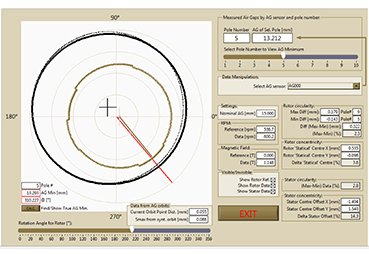
Figure 2: Air Gap analysis before application of excitation – initial condition

The eccentricity of the machine is determined by analysing data from opposite pairs of sensors during a mechanical run, when there are no influences of electrical and magnetic forces on machine geometry. The analysis also shows the vibration component as also measured from the air gap signal. This represents the dynamic center of the rotor which is in the form of an orbit as the rotor rotates around the static center of rotation marked by a cross.
The data obtained by air gap analysis gave the following results:
- Air Gap minimum is 12.39 mm (0.488 in) at 299 Degree position when pole No 5 passes
- Rotor concentricity – this was reference position so rotor is in the natural (ideal) center
- Stator concentricity 14.3 %
- Rotor circularity 3.3%
- Stator circularity 1.5%
- Vibrations in air gap – 0.253 mm (0.010 in)
These results are as shown in the analysis screen of Figure 2.
Vibrations in the air gap were also measured and compared with the measurements on the generator guide bearings namely the Upper Guide Bearing (UGB), Lower Guide Bearing (LGB) and Turbine Guide Bearing (TGB). The analysis of vibration measurements concluded that in free run the relative and absolute shaft vibrations were within acceptable criteria.
The large initial eccentricity between the rotor and stator indicated that a problem would likely be visible when excitation was applied to the machine rotor field. The rotor shape indicated that circularity of rotor was 3.3 %.
Once the field was excited it was visible (Figure 3) that the rotor center shifted its position and electrical forces changed its shape due to the magnetic field trying to pull the rotor poles to the stator. At the same time it was noted that shaft vibrations were reduced after excitation which had the effect of balancing of the machine.
Rotor balancing was performed to leave the higher vibrations when in mechanical free run such that with excitation they reduce to the point that the machine can run with relatively small vibrations at nominal power. This is a result of the orientation of the vector of magnetic unbalance which is opposite in direction from the vector of mechanical unbalance. When this occurs the machine can only be balanced well for one of these conditions. However, this approach can have a severe influence and could lead to potential bearing damage if the machine goes into over speed.
The data obtained by air gap analysis after excitation (Figure 3) gave the following results:
- Air Gap minimum is 13.203 mm (0.512 in) at 310 deg position when pole No 5 passes
- Rotor concentricity 3.6 % – rotor is off center from ideal position
- Stator concentricity 14.3 % – field flash will change rotor position
- Rotor Circularity 2.3%
- Stator Circularity 2.8%
- Vibrations in the air gap – 0.088mm (0.0035 in)
Figure 3: Air Gap analysis after field flash
The position of the rotor within the stator has changed with excitation as a result of the stator and rotor being off centre. In such cases the uneven static magnetic field produces a pulling force, commonly referred to as an Unbalanced Magnetic Pull (UMP) in the direction of eccentricity causing the center of rotation to move to a new position. The rotor rotates around this centre and at the same time vibrates which collectively is known as rotor dynamic eccentricity. From all this we see that the position of minimum air gap, calculated from the stator and rotor geometry, is in the same area as during the mechanical run.
From Figure 4, which shows bearing vibration, we can see that the shaft center (DC) shifts in the same direction in all bearings with the application of excitation. This diagram shows the difference when the excitation was removed. The orbits shown are referenced to conditions with and without excitation. This bearing behaviour fits with the air gap analysis which pointed to a conclusion that the rotor and stator are significantly off center. In fact, the stator concentricity was approximately 14% which puts this machine in a criteria considered to be critical. (Note: the criteria values are provided by Vibrosystm).
Figure 4. Shaft vibrations with excitation (Bottom left) and without (Bottom right) including shaft DC value change.
RPM and Magnetic field intensity are shown in Upper diagram (on field removal)
Analysis of shaft center (DC) before and after the field flash is in correlation with the increase of amplitudes of bearing vibrations (shown in Figure 5). This indicated that the DC movement of the shaft from the bearing center, caused by the stator and rotor being off center, resulted from a reduction of the bearing oil film. The shaft DC and air gap DC are moving in the same direction (Comparing Figures 4 and 5).
Figure 5: Vibration Signals Recorded During the Run
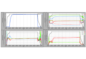
- Upper Left – RPM, Magnetic field
- Upper Right – Shaft DC
- Lower Left – Relative vibrations, Sm ax
- Lower Right – absolute bearing vibrations
DYNAMIC SHAFT DEFLECTION
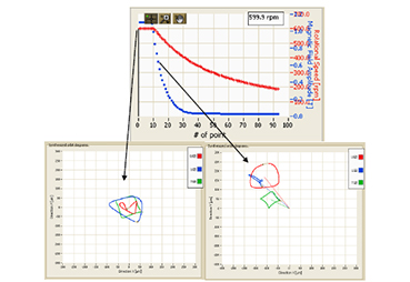
In this example, the air gap, vibration monitoring, and monitoring of electrical and process quantities was installed on a pump storage unit capable of variable speed operation.
The air gap monitoring included two air gap probes mounted at 90 degrees to each other on the stator, and one magnetic flux probe. Since the rotor design had no salient poles the air gap was measured as a displacement of the rotor body to obtain the dynamic center of the rotor.
Machine data is as follows: 185 MW, 600 RPM (± 4%), Rotor diameter is approx. 4200 mm (165.4 inches) with a nominal, designed, air gap of 13mm (0.512 in) in a “cold” condition.
Due to the nature of rotor construction, the signals from the air gap sensors are filtered with a low pass filter to reduce the influence of the surface of the rotor body on the measured values.
It has been seen from the measurements that the dynamic component of a signal in the air gap was much higher than expected. The overall peak to peak (P-P) value is approx.1.2 mm (1200um or 0.047 in), at a nominal power output of 185 MW and at 600RPM.
Figure 6. Air gap and magnetic field signals

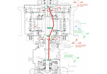
The vibrations were measured at 4 positions from the turbine guide bearing (TGB) to the Upper guide bearing (UGB) including the air gap where the signal was treated as rotor displacement. The vibration values measured on Uper Guide Bearing (UGB), Lower Guide Bearing (LGB) and Turbine Guide Bearing (TGB) were not as high when compared to the ones measured in the air gap (AG). Figure 7 shows the dynamic shaft centreline at the positions where the vibrations are measured. All the values are displayed as absolute rotor vibrations taking into consideration the displacement of the shaft and bearing bracket.
Vibration amplitudes, Peak to Peak in micro meter (P-P- μm) were measured as:
- UGB – 290 μm (0.011 inch)
- LGB – 590 μm (0.023 inch)
- TGB – 140 μm (0.0055 inch)
- AG – 1180 μm (0.046 inch)
These values indicate that in the air gap the dynamic shaft line is much different than expected when considering the values that were measured at the bearing locations. The values measured in the bearings show displacements that are less than half of the air gap amplitudes at nominal synchronous RPM. At over speeds, the values were 3 times higher in the air gap than in the bearings. This indicates that the forces in the air gap and the rotating mass have the greatest influence on the shaft dynamic center and shaft deflection. Figure 7 shows the elastic rotor line due to rotation, and shows the true dynamic deflection of the rotor since all the vibration values, from TGB to UGB, were measured simultaneously.
The deflection of the shaft is actually a dynamic component of shaft centreline. On the diagram on the right side of Figure 6 we can see the waveform of the air gap signal from the two perpendicular sensors. As the rotor surface is cylindrical (stator like) the air gap signal can be treated in the same way as a shaft displacement sensor. On the left side of Figure 6 we have a magnetic flux signal and a magnetic field pole profile analysis.
Once this dynamic rotor line is identified there is a possibility for experimental determination of the actual stiffness of the rotor shaft as obtained from the real measurements. This was based on an accurate dynamic model which was verified by measurements and later used to recognize and predict the possible faults manifested through a change in operating condition.
Figure 7. Dynamic shaft centerline
CONCLUSION
An air gap analysis can contribute to the identification of a machines condition, especially when used in combination with vibration analysis and the analysis of simultaneously measured process quantities.
To fully understand the behaviour of a hydro machine, air gap measurements are necessary both for the identification mechanical and electrical issues. Since the energy is transferred from the rotating mechanical system to electrical, we can usually detect the same fault or problem by measuring both groups of quantities. The combination of these measurements will give full insight into the machine dynamics and will lead to the source of the problems. Poor design and assembly can reduce the life of the machine and being aware of the problem source through on-line monitoring can help maintenance people to define the machine availability/reliability and plan any necessary repairs. By analysing a change in unit condition during different operating regimes the maintenance engineers is assisted in identifying the changes caused by the fault or weakness while still in its early stages. However the analysis of data on hydro machines has to be adjusted to take into consideration special designs as every machine, even if the “same” in design, has a completely different response.
Two examples described in this paper show that air gap analysis can help in defining and determining the source of a problem and, in combination with vibration measurements, can help in defining the correct manner for data interpretation.