
Copyright Material PCIC Europe
Paper No. PCIC Europe LO-101
Abstract – Many tests have been developed over the years to evaluate the condition of rotor and stator windings in motors and generators to anticipate winding failure. Some are off-line and can only be performed when the machine is shut down, and sometimes partly dismantled. Some tests are on-line (performed during normal operation of the machine) and have the advantage that production is not lost to evaluate the winding condition. This paper discusses the advantages and disadvantages of off-line versus on-line testing. The main off-line tests for stator windings include insulation resistance, polarization index, dissipation factor, and partial discharge. Depending on the type of rotor winding, the rotor off-line tests include the insulation resistance, RSO and pole drop tests. The range of on-line tests is more restricted, but includes the partial discharge, endwinding vibration, air gap magnetic flux and current signature analysis tests. The paper describes each test, with more detail provided for the newer tests that have recently been introduced or significantly improved. Important changes to IEC and IEEE standards concerned with these tests are also outlined. The conclusion is that although a large number of tests currently exist, no single test will find all the possible winding problems. Furthermore, predicting end of winding life based solely on tests seems to be an unrealistic dream and so visual inspections are often required to confirm the findings from diagnostic tests.
Index Terms — motor winding condition assessment, on-line testing, off-line testing.
I. INTRODUCTION
Although most large motors and generators are expected to operate 20 or more years, failure of rotor and stator windings may occur in just a few years due to premature aging [1]. It is usually the electrical insulation in the rotor (if present) and stator windings that degrades and leads to winding failure. Since most squirrel cage rotor windings are not insulated, mechanical failure of the rotors bars, shorting rings, or the connections between them are the most common causes of failure in this type of winding. To reduce the risk of in-service failures, and to provide assurance that new or rewound motors have been properly manufactured, a number of diagnostic tests can be performed to detect aging problems that may lead to failure, usually with months or years of advance warning. By using these tests, in combination with older test techniques such as insulation resistance and polarization index testing, unexpected in-service winding failures can be significantly reduced, increasing chemical and refinery plant reliability, thus reducing costs due to lost production. Such testing can also help to establish the optimum time for winding replacement, often delaying a rewind for many years.
There are two kinds of tests: on-line and off-line. The advantage of on-line tests is that they facilitate predictive maintenance, i.e., condition based maintenance, by identifying those machines that are most in need of offline testing or repairs. Unfortunately, on-line tests are not capable of detecting all winding problems – for example, problems at the neutral end of the stator winding or purely ground insulation problems on synchronous rotors. Thus, a short turnaround once every several years for off-line tests and limited visual inspections is still prudent. Stator winding tests are usually performed to detect problems in the electrical insulation. Rotor winding tests are to detect breaks in squirrel cage windings and problems with insulation in synchronous motor salient pole windings. Nine of the most useful tests to assess stator and rotor winding condition for motors rated 3.3 kV and above, together with visual inspections, are described in this
paper.
II. ON-LINE TESTS
A. On-Line Partial Discharge Test
Partial discharge (PD) testing is one of the best methods to assess stator winding insulation condition in machines rated 3.3 kV and above. PDs are small electrical sparks which occur in conventional 60 Hz stator windings rated 3.3 kV or higher [2-4]. PD is negligible in well-made stator windings that are in good condition. However, if the stator winding insulation system has deteriorated due to overheating, coil movement, contamination, or poor manufacturing, then PD will occur. An on-line PD test cannot normally find problems associated with stator endwinding vibration or metallic debris left in the machine. It is also of limited use for detecting stator winding problems that are not at the line end of the stator, since PD only occurs in coils operating at high voltage. PD testing is also of no use in synchronous rotor windings, again because they operate at too low a voltage to initiate PD.
A PD test directly measures the pulse currents resulting from PD within a winding. As described in the recently introduced IEC 60034-27-2 as well as the recently revised IEEE 1434, there are a large number of on-line PD test methods [2-4]. The measurement of PD in inverter fed motors is especially a challenge due to the severe interference from the inverter switching devices [5].
Partial discharge only occurs when an air-filled void occurs within the stator insulation system or at the surface of the insulation. When a PD pulse occurs, there is a very fast flow of electrons from one side of the air filled void to the other side. Since the electrons have charge and are moving close to the speed of light across a small distance, a current pulse results which has a very short duration, typically a few nanoseconds. A Fourier transform of a current pulse generates frequencies up to several hundred megahertz [2].
In a PD test on complete windings, the most common means of detecting the PD currents on conventional 50/60 Hz stators is to use a high voltage capacitor connected to the stator terminal (see Fig. 1). Typical capacitances are 80 pF to 1000 pF, with the 80 pF capacitor being the most common. The capacitor has a very high impedance to the high AC voltage in the stator, while being a very low impedance to the high frequency PD pulse currents. The output of the high voltage capacitor normally drives a resistive load, typically 50 ohm. The pulse current that passes through the capacitor will create a voltage pulse across the resistor, which can be displayed on an oscilloscope, frequency spectrum analyzer, or other display device. The bandwidth of the detector is the frequency range of the high voltage detection capacitor in combination with the resistive load. Early detectors were sensitive to the 10 kHz, 100 kHz or 1 MHz ranges. Modern detectors can be sensitive up to the very high frequency (30-300 MHz) range. If surge capacitors are installed in the motor terminal box, a high
frequency current transformer is sometimes installed on surge capacitor grounds to detect the PD [2].
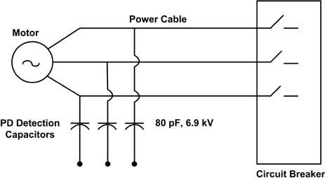
Fig. 1 – CSA of Motor with Broken Bars
In an on-line test, electrical interference from the power system is likely to be mixed with the stator winding PD signals. The noise is due to electrical sparking anywhere in the plant (for example from slip rings or poor electrical
connections), PD from the switchgear and the switching in variable speed drives. To reduce the risk of false indications of stator winding problems due to this noise, it is important to have a noise suppression system. Several are discussed in the IEC and IEEE standards [2,3], but by far the most common noise suppression system used on motors today is called the “pulse shape analysis” method where PD pulses in the stator are discriminated from external noise based on the width of the detected pulses in nanoseconds [1-3].
Some PD pulses are larger than others. In general, the magnitude of a particular PD pulse is proportional to the volume of the void or defect in which the PD occurred. Consequently, the bigger the detected PD pulse, the larger is the defect that originated the discharge. Smaller defects tend to produce smaller PD pulses. During the test, the smaller PD pulses are normally ignored. A PD test can indicate the condition of the insulation at the most deteriorated portion of the winding, since failure is likely to originate at the biggest defects, and not at the smaller defects. An important measurement in a PD test is the peak PD magnitude Qm, i.e., the magnitude of the highest PD pulse [2,3]. The PD test is a comparison test. One can determine which phase has the highest Qm, and thus which phase has the greatest deterioration. One can also compare several similar machines with the same or similar voltage rating to see which has the highest PD.
Tables of PD severity vs. rated machine voltage have been published for machines equipped with 80 pF sensors and using the pulse shape analysis noise suppression method [1]. These tables enable a rough indicator of which machines have high levels of PD. Finally, one can compare the PD from the same stators over time, i.e., trend the data. In general, if the PD doubles every six months, then the rate of deterioration is rapidly increasing.
An important limitation of on-line PD measurement is that the sensors and instruments from different vendors are almost always incompatible [4]. Another is that the capacitive sensors are connected to the machine terminals, and must therefore be very reliable. The IEEE and IEC standards describe the tests needed to ensure that the PD sensors will not cause failure [2,3].
B. Current Signature Analysis
The main failure process in fabricated squirrel cage induction (SCI) motor rotor windings are the cracks in bars, short-circuit rings or the brazed or welded connections between them that develop due to motor starting and the resulting thermal expansion and contraction of the rotor winding. In cast aluminum rotors, large voids in the bars or short-circuit rings resulting from an inadequate casting process, can also lead to failure. Current Signature Analysis (CSA) testing has revolutionized the detection of the cage winding problems. CSA is done on-line at close to normal full load. The current in one motor phase is analyzed for its frequency content (Fig. 2). The presence of defective rotor windings during normal operation of the motor is indicated by specific frequencies in the current. Thomson pioneered current signature analysis in the late 1970s [6].
During normal motor operation, the current flowing in the stator winding not only depends on the power supply and the impedance of the stator winding, but also includes currents induced in the stator winding by the magnetic field from the rotor. Thus, the stator winding is a probe for problems in the rotor. In CSA, the currents that flow through the stator to drive the rotor are separated
from the currents that the rotor induces back into the stator if there is a problem. This separation is accomplished by measuring current components at frequencies other than the 50/60 Hz power frequency, using high-resolution frequency spectrum analyzers [6,7].
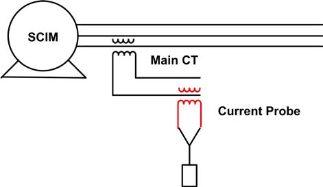
Fig. 2 Current Measurement for CSA
From conventional SCI motor theory, the frequency of the current in the rotor winding (f2) is at slip frequency, and not at the supply (50/60 Hz) frequency, that is:
f2 = sf1 (1)
Where s = per unit slip and f1 = supply frequency (50/60 Hz). The rotor currents in a cage winding produce a 3-phase magnetic field, which has the same number of poles as the stator field but is rotating at slip frequency with respect to the rotating rotor. If rotor current asymmetry occurs, then there will be a resultant backward (i.e., slower) rotating field at slip frequency with respect to the forward rotating rotor. Asymmetry results if one or more of the rotor bars is broken, preventing current from flowing through the one or more slots. With respect to the stationary stator winding, this backward rotating field at slip frequency (fsb) with respect to the rotor (as well as a torque oscillation) induces currents in the stator winding at:
fsb = f1(1±2s) (2)
The ±2sf1 components of this formula are referred to as a twice slip frequency sidebands due to broken rotor bars, or short-circuit rings. The stator current is thus modulated at twice the slip frequency. It is, however, important to note that if the rotor core has the same number of support spider arms as the number of stator winding poles, sidebands with the same frequencies and similar magnitudes as those from broken bars will result.
Typically, the sidebands are only 1 Hz or so away from the very large power frequency component and the sideband currents are typically 100 to 1000 times smaller than the main power frequency current. Consequently, exceptional dynamic range and frequency resolution is needed to accurately measure the sideband peaks due to broken rotor bars. For this reason current magnitudes are
measured in dB. If there are no cage winding breaks, then there will be no or very low-level sidebands. If significant sidebands are present (dB difference between fundamental and average sideband height ≤ 45 dB), then cage winding breaks are likely (Fig. 3).
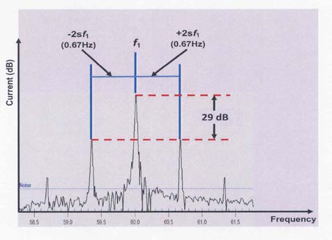
Fig. 3 CSA of Motor with Broken Bars
To detect breaks in rotor bars or the short-circuit rings, the slip frequency must be accurately known. Present day CSA monitors have proprietary means of estimating slip from the current itself [7]. This greatly improves the ease of performing CSA. Some of these methods are effective, but many have been shown to produce errors for small motors, motors that have a large number of
poles, or those driving pulsating loads such as reciprocating compressors. Recent innovations have reduced the false indications produced by these effects [7].
Recently an ISO standard was published that describes the test and provides guidance for interpretation [8]. As with most tests, it is best to trend the sideband magnitude over the years. If the sideband increases over time, then it is reasonable to expect that bars, or short-circuit rings have broken in more locations. At some point there may be enough breaks in the rotor cage winding that the motor may fail to start or some winding metal may fly off the rotor, destroying the stator.
C. Magnetic Flux Test to Detect Synchronous Rotor Shorted Turns
Unlike squirrel cage rotor windings which do not have insulation, synchronous motors and generators have rotor windings that have both turn and ground insulation. As for stator windings, these insulation systems gradually age over time due to thermal and mechanical stresses, as well as due to contamination. Usually, the turn insulation fails first. As more turn shorts occur (a turn short does not trip a machine), eventually a rotor ground fault occurs which does normally result in a machine trip.
Shorted rotor turns in synchronous rotor windings can be detected by magnetic flux monitoring, which was first invented by Albright [9]. In this test a small, statormounted “flux” coil is placed in the airgap between the rotor and the stator during a short shutdown. As each rotor coil passes the flux coil due to rotation, it induces a voltage in the flux coil that is proportional to the flux in that particular rotor coil. If there is a turn short in a rotor coil, there will be a lower magnetic flux and hence less voltage induced in the flux coil.
There are two versions of the flux test – one for round rotors (two- and four-pole machines) and another for salient pole rotors (usually four or more poles) [10]. Since the magnetic flux in the airgap also depends on the machine’s real and reactive power, plus changes in the airgap distance, methods have been developed to suppress these influences by comparing one pole (or coil) against another pole (or coil) of the opposite polarity [10]. These normalized readings can then be trended over time to determine if more turn shorts are occurring. If more shorts are occurring, it increases the likelihood that a rotor ground fault is imminent. The method allows the shorts to be located to a particular pole and/or coil. There are no IEEE or IEC standards for this on-line test.
D. Stator Endwinding Vibration Monitoring
The stator coil endwindings (that is the portion of the coils outside of the stator core) are subject to mechanical forces that tend to make them vibrate. The biggest force is due to the interaction of the magnetic fields from the current in adjacent coils in the endwinding, which produces a twice frequency force (i.e., 100 Hz in a 50 Hz machine). Another force can sometimes occur if there is high rotor vibration at 1X rotational speed, which is then transmitted from the bearings to the stator frame and core – thus to the stator endwinding. If the endwinding coils are well-supported, then these forces do little harm. However, if the stator was not well built and there are natural frequencies near the force frequencies at 50 Hz (for a two-pole machine) or 100 Hz, then the endwinding vibrates, causing the insulation to abrade and/or the copper conductors to fatigue crack. In the past 10 years, endwinding vibration has resulted in more insurance company claims than any other failure mechanism [11].
To detect if the endwinding vibration is excessive, accelerometers can be installed at critical locations. The vibration sensors are normally of the fiber optic type, since the high voltages make installing grounded piezoelectric sensors risky. The sensors are located at areas of maximum looseness, as determined from a bump test [11]. The sensors can be measured by a continuous monitor, or by periodically connecting the sensors to conventional portable vibration instruments (spectrum analyzers).
An IEC standard 60034-32 is in development to describe on-line endwinding vibration monitoring. When published, it will not give safe vibration limits. However, IEEE 1129-2014, which has recently been published, indicates that if the vibration exceeds 250 μm peak-topeak, then action is needed.
III. OFF-LINE TESTS
A. Insulation Resistance (IR) and Polarization Index (PI)
The insulation resistance test is the most widely used diagnostic test for stator and synchronous rotor windings. This off-line test successfully locates pollution and contamination problems in such windings. In this test, two properties are measured: the insulation resistance (after one minute of voltage application) and polarization index, which is the ratio of the 10 minute and one minute insulation resistances. Both measurements are performed with the same instrument, and are usually done at the same time. IEEE 43-2013 describes the test method and basic interpretation [12]. This IEEE standard has been significantly changed from older versions.
The IR test measures the resistance of the electrical insulation between the copper conductors and the core of the stator or the rotor body. Ideally this resistance is infinite, since after all, the purpose of the insulation is to block current flow between the copper and the core. In practice, the IR is not infinitely high. Usually, the lower the resistance, the more likely it is that there is a problem
with the insulation.
Measuring the one minute insulation resistance (R1) has proved to be unreliable, since it is not trendable over time. The reason is that IR is strongly dependant on
temperature. A 10o C increase in temperature can reduce R1 by 5 to 10 times. Worse, the effect of temperature is different for each insulation material and type of contamination. Although some ‘temperature correction’ graphs and formulae are in the IEEE 43, they are acknowledged as being unreliable for extrapolation by more than 10oC or so. The net result is that every time R1 is measured at different temperatures, one gets a completely different R1. This makes it impossible to define a scientifically acceptable R1 over a wide range of
temperatures. It also makes trending R1 meaningless unless the winding is always tested at the same temperature.
The PI is less sensitive to temperature. If ten- and oneminute IRs are measured with the winding at the same temperature, which is usually very reasonable to assume, then the ‘temperature correction factor’ will be the same for both, and will be ratioed out. Therefore, PI is relatively insensitive to temperature. Thus the trend in PI over timeis a good indicator of insulation degradation due to contamination.
As discussed in IEEE 43, experience shows that if the PI is about one, then the leakage current over the winding is large enough that electrical tracking will occur. Conversely, if the leakage current is low after 1 minute, then PI will be greater than 2, and experience indicates that electrical tracking problems due to winding contamination are unlikely. In a modern stator winding, the one minute insulation resistance should have an R1 > 100 MΩ, while for synchronous rotor windings, this value should be > 5 MΩ when corrected to a temperature of 40°C per IEEE 43-2013. For form-wound stators, the PI should be >2 unless the IR ≥ 5000 MΩ [12].
B. Off-Line Partial Discharge (PD) Test
The off-line PD method is similar to the on-line PD test discussed above. However, it is performed with the generator or motor in some state of disassembly. There are four versions of the off-line PD test:
1) Off-line PD test on the entire stator to quantify the PD activity.
2) TVA (corona) probe test to locate the PD.
3) Ultrasonic probe test to locate the PD [15].
4) Blackout or ultraviolet imaging to locate surface PD.
The first test is similar to the on-line test in that a high voltage capacitor is used to detect the PD. The stator winding must be energized to at least rated line-to-ground voltage, which means the PD can occur in any coil (and not just coils connected to the phase terminal as is the case for an on-line test). The test method is described in IEC 60034-27 [13]. This off-line PD test is now being used both by motor and generator manufacturers as well as by end-users of new motors and replacement stator windings as a quality check for individual coils and global VPI stators, to determine whether adequate resin impregnation has been achieved. If on-line PD sensors are not installed on a machine, this test can also be done periodically to assess the degree of insulation aging. No pass/fail criteria have been established, however, an increase in PD over the years indicates that aging is occurring.
The last three tests above are primarily used to locate where in the winding any high PD (as found by the on-line or off-line PD tests) is occurring.
C. Power Factor / Dissipation Factor Tip-Up
The insulation in a stator winding may be approximated by treating it like the dielectric in a capacitor [1]. In addition to its capacitance, a real capacitor has a small ‘dielectric loss’ which depends on molecular motion in any particular insulation material. As such, a low voltage dielectric loss measurement (as measured by a dissipation factor (DF) bridge or a power factor instrument) does not have much diagnostic value.
The test is most useful when performed on a stator coil or complete winding at both low and high voltages and the increase in value with voltage (tip-up) is evaluated. The magnitude of the increase with voltage is a function of the amount of partial discharge activity in the stator winding insulation system. Traditionally such tests have been performed on each winding phase, if possible, at voltages of about 25% (which should be below the PD Inception Voltage) and 100% of the rated phase-to-ground voltage.
There is an important limitation of the DF tip-up test. Stator windings rated above 6 kV generally have a coating of electric stress grading material that interfaces with the slot semi-conductive coating. This coating is usually made from a silicon carbide material with nonlinear resistive characteristics. During PF or DF tip-up testing the power loss in this coating will change as the voltage applied to the winding is increased. This effect may produce higher tip-up values that could be mistaken to indicate insulation degradation. Unfortunately, there is
no way to overcome this effect when testing stator windings (it can be corrected for in tests on individual coils). However, any increase in the tip-up over the years may mean that higher PD activity is occurring.
D. AC Pole Drop Test for Salient Pole Rotors
The pole drop test is used to detect shorted turns in salient pole windings and involves applying a singlephase ac voltage of around 120 to 240 V across the complete winding and measuring the voltage drop across each pole [1]. Since the test circuit is mainly inductive, one or more shorted turns in a pole winding
will create a significant reduction in inductive impedance of the winding on the pole, and reduce the voltage drop across it. The acceptance criteria for this test is that no individual pole shall have a voltage drop > ±10% of the average value of all the poles.
One of the disadvantages of this test is that it may not detect pole winding turn shorts that are only present under the influence of the cetrifugal forces present during rotation in service. This test deficiency may be overcome by performing the test with the rotor supported horizontally at four rotor positions 90° apart. This makes use of gravitational forces to perhaps induce shorts in pole turns in at least one of these four positions.
As discussed in Section II.C, shorted rotor winding turns do not fail the machine. However, if the number of shorted turns increases over time, it is likely that the
ground insulation will fail, tripping the machine.
E. RSO Test for Round Rotors
The RSO test is used to find shorted turns in 2- and 4-pole round rotors [1]. It is similar to the time domain reflectometry test commonly used to find the location of shorts in power cable and communication cable circuits. In the RSO test, a short risetime voltage pulse up to a few hundred volts is injected into the rotor winding (usually at the sliprings, if present). This pulse will travel along the winding at close to the velocity of light. When a shorted turn is encountered, it changes the surge impedance of the winding at that point. This impedance mismatch will create a reflection that travels back to the injection point, changing the waveform. By comparing the waveforms from the positive and negative sliprings, it is often possible to detect the presence of the shorted turns, as well as their approximate locations. This test can be performed with the rotor at standstill or rated speed if sliprings are installed. The test is reasonably subjective and greatly depends on the experience of the tester.
F. Hipot and Surge Tests
All the on-line and off-line tests mentioned above are “diagnostic” tests, that is, they detect degradation of the winding well before winding failure occurs. There is another class of tests that apply a higher than normal voltage to the winding insulation to determine if the insulation can withstand the overvoltage. These tests include the AC hipot (IEC 60034-1), the DC hipot (IEEE 95) and the surge withstand (IEC 60034-15) tests. These are go-no go tests, and essentially provide no diagnostic information. Failure of any of these tests implies a rewind (or at least the removal of the failed component) needs to be done.
IV. OFF-LINE VERSUS ON-LINE TESTING
All the rotor and stator tests in Section III are performed when the machine is not operating. Many of the tests can be done from the machine terminals,
avoiding full or partial disassembly of the machine. However, some of the tests can only be done with the machine at least partly disassembled. Thus, all of the
off-line tests, by definition, require at least a short turnaround.
In contrast, the on-line tests are performed during operation of the motor or generator. Therefore, no turnaround is needed, although for some monitors, the
operating condition of the machine is changed to extract the greatest amount of diagnostic information.
In general on-line testing is preferred because:
1) No machine shutdown is needed to determine winding condition, at least for the failure mechanisms the monitoring can detect.
2) Usually, the cost of acquiring the diagnostic data is cheaper than for off-line tests since, generally, one person can collect the data and it usually takes just a few minutes. In modern on-line testing, data collection is often automated. In
contrast, off-line tests may require a few people to isolate the machine, get the test equipment to the machine, hook it up, and run the test.
3) It facilitates predictive (or condition-based) maintenance, since one can determine which machines are in need of off-line testing and repairs without taking the machines out of service.
4) The stresses that occur in service (temperature, voltage and mechanical forces) are present. For example, it is impossible for an offline test to properly simulate the AC stress distribution in the winding that occurs in service. An AC voltage applied to simulate the normal phase-to-ground stress in the slot will result in a
60% lower voltage between the line-end coils in different phases in the endwinding than occurs in service.
The disadvantages of on-line testing are:
1) Usually, there is a higher capital cost, since sensors and sometimes monitoring instruments must be installed on each machine, in contrast with off-line testing where one instrument can be shared for tests on a number of machines.
2) Not all failure processes can be detected with existing on-line monitoring. Thus, unexpected failures can go undetected if all diagnostic information comes only from online monitors.
3) Since on-line tests are often connected to plant SCADA systems, and the communications buses and protocols change frequently, continuous effort
is needed to keep the system functional.
A judicious mix of off-line tests and inspections, together with on-line monitoring is needed to implement predictive maintenance. The mix will change from plant
to plant, and even from machine to machine within the same plant, as one considers the importance of the machine to the plant and other economic criteria.
V. ESTIMATING WINDING REMAINING LIFE
Determining the winding condition or estimating the expected remaining useful life of a winding is a common reason cited for doing on- and off-line tests. For
example, a plant manager wants to know if a motor that is more than 15 years old can continue to operate for the foreseeable future, or if a new motor or rewind is needed. The manager may also ask how long the existing motor will run before failure occurs, since the life of the winding can be maximized. Testing helps answer these questions. Unfortunately, testing and monitoring alone is not likely to give a definitive answer [14]. One reason is that the end of winding life depends on when a transient occurs in the power system, or when an operator makes a mistake. This transient may then trigger the failure of weakened insulation in the rotor or stator. In the absence of a voltage or current transient, the insulation may continue to fulfill its function for many years – partly because mica is such a robust insulation. Clearly, tests on the rotor and stator windings will not allow one to predict when a transient may occur from the power system.
In addition, determining remaining life is also difficult because most of the tests measure a symptom, not the root cause of the failure. Aside from hipot and surge
testing, none of the other tests can determine if a rewind or new machine is needed. Some human intervention to correlate results from different tests, to perform a visual inspection and to perform an economic evaluation is needed to make this determination.
Therefore, assessing winding condition must have a more limited objective. This could be to determine if winding deterioration has occurred. In some cases, the
severity of the failure process can be determined and, perhaps, one can then estimate the ‘risk of failure’. Risk of failure means the probability that the motor or generator will fail if a transient or operator error occurs.
VI. CONCLUSIONS
The main advantage of performing on-line tests, as opposed to off-line tests, is that they can detect many aging mechanisms in rotor and stator windings under
actual operating conditions, with no machine shutdown. This avoids the high costs associated with taking the machine out of service and allows the detection of some rotor winding mechanisms that are more difficult to identify when the machine is shut down. Off-line tests can confirm the presence of winding degradation identified from on-line tests and other types of degradation not
identifiable from on-line tests.
Visual inspections are required to determine the severity of component aging and to identify some aging mechanisms that cannot be detected by on- or off-line
tests. This latter reason makes it advisable to perform periodic visual inspections on all generators and critical motors every few years to ensure that such aging
mechanisms are detected before they cause a failure.
VII. REFERENCES
[1] Greg C. Stone, Ian Culbert, Edward A. Boulter, Hussein Dhirani, Electrical Insulation for Rotating Machines – Design, Evaluation, Aging, Testing and Repair – Second Edition, Wiley – IEEE Press, 2014.
[2] IEEE 1434-2014 Guide to the Measurement of Partial Discharges in Rotating Machinery.
[3] IEC 60034-27-2 On-Line Partial Discharge Measurements on the Stator Winding Insulation of Rotating Electrical Machines.
[4] G.C. Stone, M. Stranges, D. Dunn, “Recent Developments In IEEE And IEC Standards For Off-Line And On-Line Partial Discharge Testing Of Motor And
Generator Stator Windings”, in IEEE PCIC, San Francisco, September 2014.
[5] G.C. Stone, I. Culbert, S.R. Campbell, “Progress in On- Line Measurement of PD in Motors Fed by Voltage Source PWM Inverters”, in IEEE Electrical Insulation Conference, June 2014.
[6] W.T. Thompson, “Diagnosing Faults in Induction Motors – Engineering Ideas”, Electrical Review, Nov 1984, pp 21-22.
[7] Ian M. Culbert and Wendell Rhodes, “Using Current Signature Analysis Technology to Reliably Detect Cage Winding Defects in Squirrel Cage Induction Motors”, IEEE Transactions on Industry Applications, Vol. 43, No. 2, March/April, 2007.
[8] ISO 20958-1-2013 – Condition Monitoring and Diagnostics of Machines. Electric Signature Analysis. Part 1: Three-phase Induction Motors.
[9] D. Albright, “Interturn Short Circuit Detector for Turbine Generator Rotor Windings”, IEEE Trans PAS, Vol 90, 1971.
[10] M. Sasic et al, “Detecting Turn Shorts in Rotating Machine Windings – A New Test Using Magnetic Flux Monitoring”, IEEE Industry Applications Magazine, March 2013, pp 63-69.
[11] J. Kapler et al, “Recent Endwinding Vibration Problems in Air-Cooled Turbine Generators”, CIGRE Paper A1- 201, Aug 2014.
[12] IEEE 43-2013 Recommended Practice for Testing Insulation Resistance of Rotating Machinery.
[13] IEC 60034-27 Partial Discharge Off-Line Measurements of the Stator Winding on the Stator Windings of Rotating Machinery.
[14] G.C. Stone, I. Culbert, “Prediction of Stator Winding Remaining Life From Diagnostic Measurements”, in IEEE International Symposium on Electrical Insulation, San Diego, June 2010.
[15] Yong-Ming Yang, Xue-Jun Chen, Partial Discharge Ultrasonic Analysis for Generator Stator Windings, Journal of Electrical Engineering & Technology, Vol. 9, No.2,, pp 670-676, 2014.
VIII. VITA
Ian Culbert has been a Rotating Machines Specialist at Iris Power L.P since April 2002.At this company he provides consulting services to customers assists in product development, trains sales and field service staff and reviews stator winding partial discharge reports. Before joining Iris Power he was a motor and small generator specialist with Ontario Hydro/Ontario Power Generation from 1977 to 2002 and prior to then a motor designer with Parsons Peebles, Scotland and Reliance Electric, Canada. Ian is a Registered Professional Engineer in the Province of Ontario, Canada and a Senior Member of IEEE. He has co-authored two books on electrical machine insulation design, evaluation, aging, testing and repair and been principal author of a number of Electric Power Research Institute reports on motor repair. Ian has also co-authored a number of papers on motor electrical component on-line and off-line motor diagnostics testing and actively participates in IEEE, IEC and ISO standards development working groups.
Greg Stone (M75, SM88, F93) has a PhD in Electrical Engineering from the University of Waterloo (Canada). From 1975 to 1990 he was a Dielectrics Engineer with Ontario Hydro’s Research Division. Since 1990, Dr. Stone has been employed at Iris Power in Toronto Canada, a rotating machine condition monitoring instrumentation company that he helped to form. He is a past-President of the IEEE Dielectrics and Electrical Insulation Society, and continues to be active on many IEEE rotating machine standards working groups. He is
also active on several IEC rotating machine standards working groups, and from 2007 to 2013 was an elected member of the IEC Council Board, IEC’s governing body. He has published two books and many papers concerned with rotating machine insulation. He is a Fellow of the Engineering Institute of Canada and is a registered Professional Engineer in Ontario, Canada. (gstone@qualitrolcorp.com)
Blake Lloyd (SM85) is an Electrical Engineer with extensive experience in instrumentation and product development. In past lives, he worked in software
development and then in the Electrical Research Department at Ontario Hydro, where he was responsible for conducting research into advanced measurement,
testing, and diagnostic monitoring techniques for rotating machines and insulation systems. Since co-founding Iris Power in 1990, Blake has been one of the principle architects of Iris’s line of diagnostic test instrumentation and analysis software. He has two US patents, and has published 16 refereed papers in IEEE and CIGRE, as well as over 40 conference papers. He is current President
of the IEEE Industry Application Society and has served as Canadian Expert on IEC Technical Committee 2: Rotating Machines, WG 26. Blake received the 2010
Meritorious Engineering Award of the IEEE/IAS Pulp and Paper Technical Committee. (blloyd@qualitrolcorp.com)