
CIGRE Colloquium on Large Electrical Machines and Renewable Generation, Bucharest Romania, September 2013
SUMMARY
Generator rotor and stator windings are usually very reliable, with 30 or more years of life before major repairs or replacement is needed. However, the windings do eventually age and fail due to thermal, electrical and mechanical stresses as well as environmental factors. Traditionally utilities have employed a time-based (preventive) maintenance philosophy to detect developing rotor and stator problems. However, over the past 25 years a number of on-line monitors have been developed that can detect specific problems before failure occurs, allowing pro-active repairs or winding replacement without depending on finding the problems during a scheduled outage. This is the essence of condition-based (or predictive) maintenance. The on-line monitoring available includes: Comprehensive thermal monitoring; Magnetic flux monitoring to detect rotor shorted turns; Air gap monitoring (for hydrogenerators); Shaft voltage and current monitoring; Stator partial discharge monitoring; Stator endwinding vibration monitoring; Particulate (core) monitoring (hydrogen-cooled machines); Ozone monitoring (air-cooled machines); and Bearing vibration.
Together, these monitors can detect most (but not all) of the aging-related problems that occur in generators well before actual winding failure. The advancements in these individual monitors have been significant, which has reduced the false indication rate and reduced cost. However, almost all of these monitors operate independently. Communication between them and between plant control systems for process data required for interpretation is often difficult. In addition, even though some of the monitors may produce complimentary information (e.g. shaft voltage/current monitoring and flux monitoring), an experienced engineer is normally needed to correlate the information from these different monitors due to incompatible software platforms.
This paper discusses the design of an integrated system that can implement two or more of the above monitors into a common instrument and display platform. The implications for continued progress in implementing condition-based maintenance are discussed.
KEYWORDS
Generator, stator winding, rotor winding, condition monitoring
1 INTRODUCTION
There are a large number of possible failure mechanisms of stator windings, rotor windings and their cores in large generators [1, 2]. Some of these failure processes are due to sudden operating events (accidental shutting off of the cooling water, power systems transients, metallic debris that is left within the machine) that realistically cannot be guarded against. However, many of the failure mechanisms are due to long term aging of the electrical insulation, copper conductors and/or the stator and rotor cores/forgings. These aging mechanisms are principally driven by the currents, voltages, mechanical stresses and environmental factors which gradually reduce the electrical and mechanical strength of the insulation, copper and steel. Eventually the strength is reduced to a sufficient extent that the insulation punctures or the metal fatigue cracks and an outage occurs. Most of these failure mechanisms can be easily found and assessed during frequent minor and major outages. However, the time based (preventive) maintenance approach that is implied with such outages results in many outages that are frequently not needed since the generator is found to be in good condition. In addition, the reduced availability caused by the inspection and test outages reduces the revenue to that plant.
These disadvantages of time-based maintenance have created a desire for a move to condition-based maintenance (also call predictive maintenance), where the generator is removed from service for an inspection/test when, and only when, a condition monitor indicates a developing problem. To this end, a large number of monitors have been developed over the past 25 years to detect many (but regrettably not all) failure processes during normal operation of the generator (i.e. on-line). In the early days there were a number of issues with the credibility of the monitors (due to false positive and false negative indications), and the monitors themselves also tended to have reliability problems. However, the effectiveness of the monitors has been improving.
No single monitor can detect all possible problems in a generator. Thus many monitors are needed to detect the most likely problems. Unfortunately almost all of these monitors operate in isolation, using different communication structures, software platforms, database storage structures and information display formats. These differences between on-line monitors make it difficult for plant owners to combine the information from all the monitors to determine whether or not there are developing problems.
An effort by IEEE to create a common platform for generator condition monitoring has not been successful. IEC has undertaken no such effort, at least for the rotor and stator winding monitors. No doubt, a large generator manufacturer who also supplies condition monitors probably uses a common platform, but all analysis tends to occur at the manufacturers site, out of the control of the user.
Recognizing these factors, there seems to be a need for independent suppliers of generator condition monitoring systems to develop a common platform that can be used with a large number of on-line monitors. This paper describes one attempt at this.
2 WINDING FAILURE PROCESSES
There are probably over 30 or so distinct failure processes in generator and rotor stator windings [1, 2]. Whether a particular failure process occurs or not depends on the design, cooling system, operating environment and the past maintenance done on the machine. The most likely stator problems include, amongst others:
- Thermal aging
- Thermo-mechanical aging (load cycling)
- Loose windings in the slot
- Endwinding vibration
- Water leaks in direct cooled windings
- Electric stress coating deterioration
- Endwinding electrical tracking due to contamination
- Insufficient space between the endwindings
- Loose stator cores
- Core insulation thermal aging
The more likely rotor winding deterioration processes include:
- Thermal aging
- Thermo-mechanical aging (load cycling)
- Copper dusting
- Contamination
- Centrifugal force
Each of these mechanisms proceeds at its own rate, and often the repair process for the individual mechanisms is different. Therefore, it is important to know which mechanism is occurring (if any).
3 ON-LINE GENERATOR MONITORS
On-line generator monitoring instrumentation requirements depend on a variety of factors including machine rating, type of construction, and cooling method. These can generally be selected based on the cost and criticality of the generator and involves a balance between failure cost versus repair and lost production cost. The monitors require sensors to be installed on the components of interest. Data collection, communication, and analysis occur at regular intervals depending on the monitoring requirements, hardware capabilities and setup.
3.1 Stator monitoring
Resistance Temperature Detectors (RTDs) or thermocouples can be used to monitor stator bar temperature. Typically these are installed between the top and bottom bar in the slot and measure the highest temperature. The higher the temperature and the longer the duration at elevated temperatures, the more likely will be thermal deterioration or thermal cycling issues.
Monitoring high frequency voltage pulses in stator windings with a partial discharge (PD) monitor can measure activity that is the result of insulation deterioration inside the windings, between the windings and the slots, and on the endwindings. Small electrical sparks in air-filled voids within the insulation create small voltage pulses and as the size of the voids increases so does the magnitude of the partial discharge pulses. Simply put, where the voids are within the insulation will determine the pulse polarity and phase position of the partial discharge which can indicate various failure mechanisms including thermal cycling, thermal aging, looseness, contamination, etc. There are many on-line PD monitoring systems for generators. The most common uses either capacitive sensors directly on the high voltage bus (2 per phase to identify system noise based on pulse direction) or antennae installed in the slots with the line end bars (1 per parallel per phase, no noise separation required) [3]. Given that the failure mechanisms associated with partial discharge are slow in developing, a monitor with continuous data storage is not necessary. Instead smart data acquisition should be incorporated to collect data automatically to provide meaningful trend data at various stages of the generator load cycle.
Ozone gas is a by-product of surface partial discharge in air-cooled machines. Ozone monitoring will indicate partial discharge on the surface of stator windings that is the result of loose windings, semi-conductive deterioration, and insufficient spacing in the endwinding. Sensors installed within the generator enclosure or in the air exhaust can continuously measure ozone concentration. Care must be taken when evaluating concentration levels as generator operating voltage, air humidity, and power factor will affect the ozone produced by a stator winding [1].
“Generator Condition Monitors” or GCMs are used to detect stator core lamination insulation burning in hydrogen-cooled machines. They detect particulates from burning core lamination insulation. Together with tagging compounds, they can also be used to detect hot spots on the rotor and stator windings [1, 2].
Stator endwinding vibration issues are found on large generators with especially long winding overhangs that are not sufficiently supported. Monitoring this vibration, by installing sensors on the endwindings, connections, support brackets, water manifolds, etc, will indicate when the support structure loosens. There is a practical limit to the number of locations and components that will be monitored so off-line impact testing should be incorporated to determine the locations of the components that are most likely to vibrate at maximum amplitudes during operation [4]. Metallic accelerometers used to collect vibration data may compromise the electrical clearances of the endwinding to ground and can result in partial discharge. Instead, fiber optic accelerometers should be used as they are not sensitive to the electrical fields present in the high voltage stator endwinding area. Historically, a double integrated signal from acceleration to displacement has been used to assess the structural integrity of the stator endwinding support system, but with the advancement of fiber optic technology more data at a broader frequency is being collected resulting in a need to not only assess endwinding displacement, but velocity and acceleration as well.
For certain direct-water-cooled windings, it is possible to detect sensitively when small water leaks may be occurring which can degrade and fail the stator ground insulation. To determine if this deterioration process is occurring can be inferred from the leakage of hydrogen into the stator cooling water. One major manufacturer has developed such a system called SLMS-HP, based on an undisclosed method [5]. The system can apparently detect hydrogen to water leaks as low as 6000 cm3 per day.
3.2 Rotor monitoring
Rotor winding temperature can be monitored by accurately measuring the voltage and current applied to the slip rings. The rotor winding resistance, calculated with Ohm’s Law, will vary with temperature. Once calibrated, the average rotor winding temperature can be inferred. In those machines without slip rings, the voltage and current feeding the rotor can be measured indirectly by measuring excitation voltage and current.
Vibration monitoring with sensors installed on the bearing housings and shaft journals will monitor the forces generated from a generator. These forces cause vibration and may change in direction with time, change in amplitude with time, result in friction between rotating and stationary components, cause impacts, or cause randomly generated vibration. The vibration amplitudes are proportional to dynamic forces meaning that increased forces will reduce generator life. In general, problems that cause high vibration amplitudes are rotor unbalance, shaft misalignment, looseness, bearing wear/misalignment, rubbing, and electrical problems. Specifically, in two-pole generators, bearing vibration can indicate the presence of shorted turns in the rotor winding caused by thermal or thermal-mechanical problems, copper dusting and/or contamination. Vibration monitoring is often part of the protection system, as high vibration at these locations should automatically trip and shut down the generator to prevent catastrophic failure.
Rotor flux monitoring will provide information on the integrity of rotor winding turn insulation. A turbine generator rotor consists of a solid forging made from magnetic alloy steel and copper windings, assembled in slots machined in the forging. Problems with rotors result from exposure of winding copper and insulation to high centrifugal loads and thermal expansion forces, leading to breaks in the winding insulation and to copper cracking and contamination. A magnetic flux sensor installed on a stator tooth in the air gap is sensitive to radial flux density as the rotor passes by the probe. Shorted rotor winding turns results in reduced slot leakage flux and is an indication of insulation failure in the rotor winding. In conventional flux monitoring, distortion of the radial flux signal is minimal where the air gap flux density curve crosses through zero which is a function of generator load. Because of this, it is required to take multiple readings at various generator load points for maximum sensitivity to shorted turns, but recently it has been demonstrated that accurate detection of rotor winding shorted turns can be obtained with a reduced need to vary the load on the generator with suitable instrumentation and algorithms [6]. Alternatively, smart triggers can be used to automatically capture the flux information during normally occurring load variations.
Shaft current and voltage monitoring will help detect poor grounding of the shaft and avoid bearing and seal damage when high shaft voltage is present by monitoring the condition of the shaft grounding brush. Measuring shaft current may require a modification to the grounding brush while a voltage sensing brush usually needs to be installed to transition shaft grounding protection to a shaft monitoring system. Shaft current and voltage monitoring should be continuous as the duration can be quite short from when a grounding brush begins to wear to when the stray currents start flowing between the shaft and the bearings. The resulting bearing pitting may cause permanent damage to the shaft and bearings.
4 INTEGRATED PLATFORM
Deterioration of generator components is usually a relatively slow process where the time between condition detection and failure may be several years. Thus, measurements which are done periodically can be adequate for detecting problems. However, a continuous, automated, and fully integrated monitoring system has many advantages:
- Site Operations and Maintenance staff in plants are under increasing work load. Integrated monitoring systems, allow automated measurements to be made, sparing time and expense of having to send personnel to the plant.
- Monitored conditions are often affected by operating conditions, including winding temperature, load, voltage, current, etc. An automated monitoring system avoids this problem by continuously measuring the generator operating conditions, and then trending and correlating the condition measurements taking into account the operating state of the machine.
- Collecting data during varying conditions can itself be useful in the data interpretation process. For example, for stator partial discharge measurements at different load points, the winding experiences different stator bar forces, thus winding looseness can be inferred by comparing full-load and no-load test results. Such an integrated automated monitor gives maintenance engineers a more complete picture of the machine’s condition when using data collected in this manner.
- Expert systems or intelligent software can be used to correlate data from various sensors into one platform. An integrated condition monitoring system can augment the capabilities of more complex data types such as PD, flux, and endwinding vibration by processing data into simplified information. An integrated platform will corroborate fault diagnosis from multiple monitors to provide a cooperative approach to condition-based monitoring.
An integrated platform to collect data from a range of sensors can be used for trending and assessing the stator and rotor conditions. Each generator to be monitored requires one instrument to be mounted outside of the machine, near the sensors. Coaxial and fiber optic cables connect the sensors to the instrument. The instrument raises an alert if a particular activity is more than a predefined value for the current machine operating conditions. Ethernet is used to connect the monitor to the plant local area network for configuration and data downloading. This allows personnel in distant offices to define or change trigger conditions and alert levels, as well as download test results for display and analysis. The archived data can also be downloaded locally over a USB port. The software included with the instrument is a single platform for generator definition, sensor configuration, data downloading, and data analysis. A common Microsoft Access database is used to archive data from all technologies along with relevant operating data. Viewers for looking at historical trends, correlating data, and performing detailed analysis are used to assess the generator health. A layout of this system is below, Fig 1.
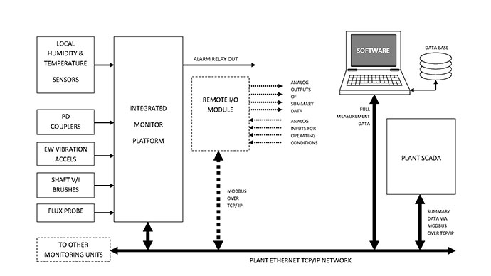
Fig 1. Layout of generator integrated monitor platform
Using such a platform, it is often possible to predict “expected” values for sensors based on mathematical models of machine parameters. These predicted values can then be compared to the actual measured values and deviations analysed to detect failure modes. For example, the predictions of stator endwinding vibration can be made based on the stator current and winding temperature of the generator. If the temperature is constant, Ampere’s force law can be used to calculate the force between 2 current-carrying conductors which is directly related to vibration. This relationship with collected data is shown in Fig 2. Once calibrated with baseline data, any change in current (force) can be used to calculate the expected endwinding vibration and any deviation can be attributed to a change in the endwinding structural support structure. For many sensors, the alarm thresholds may also be significantly different depending on the operating mode of the machine.
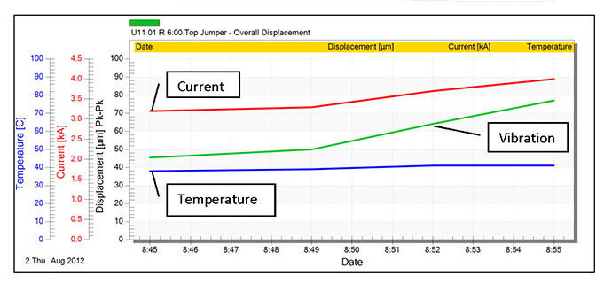
Fig 2. Endwinding vibration, stator current, winding temperature over time
The assessment of the generator stator insulation system is enhanced by having access to an extensive PD database. The collective experience and results are regularly summarized in statistical tables and available to all users [7]. This data is also used to automatically configure alert levels ensuring objective interpretation of insulation condition. Smart triggers are utilized to collect data at various generator load and winding temperature conditions.
Advanced algorithms can be employed to analyse flux data on rotor windings regardless of load changes. This technology provides the highest accuracy in identifying rotor shorts regardless of flux density zero crossing location. Additionally, smart triggers are also used to collect data automatically at various generator loads.
Endwinding vibration data is continuously collected from fiber optic accelerometers and alerts on high overall displacement. Additional analysis capabilities enable displays in displacement, velocity or acceleration across the frequency range of interest.
Modbus over Ethernet protocol is included for interfacing with third party applications allowing for the ability to receive machine operating condition data such as active power, reactive power, stator voltage, winding temperature, and hydrogen pressure from plant systems. This capability improves trending data by providing context to the PD, flux, and endwinding vibration measurements. Signals proportional to the monitor’s summary values and status data can also be transferred to plant systems for central trend display. A block diagram for the signal communication possibilities between the monitor and plant system is below, Fig 3.
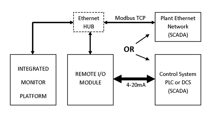
Fig 3. Block diagram of signal communication with integrated monitor
5 Conclusion
The primary benefits of incorporating on-line monitoring systems are to avoid unplanned outages, and to extend the time between planned outages. Maintenance and repair costs can also be saved as generally they are less if action is taken at earlier stages of generator deterioration.
Benefits of on-line generator monitoring include:
- Extended Life: by detecting the onset of problems so repairs can be carried out before major damage occurs.
- Maximized Time between Outages: as equipment is removed from service less frequently than other maintenance schemes (breakdown, time based).
- Reduced Repair Costs: by detecting problems at an early stage.
- Avoiding Catastrophic Failures: by detecting deterioration at the earliest onset.
- Reduced Risk of Damage during Outage: as the disassembly, outage and reassembly can result in inadvertent damage.
Integrating multiple monitoring technologies provides the benefit of not only detecting subtle changes in the generator early enough to prevent lost production, but increasing the confidence of the generator condition assessment by taking a collaborative approach to condition-based monitoring.
BIBLIOGRAPHY
[1] G.C. Stone, E.A. Boulter, I. Culbert, and H. Dhirani, Electrical Insulation for Rotating Machines – Design, Evaluation, Aging, Testing and Repair, John Wiley and Sons, Inc., Publication, 2004.
[2] G. Klempner, I. Kerszenbaum, Handbook of Large Turbo-Generator Operation and Maintenance, 2nd Edition, Wiley-IEEE Press, 2008.
[3] S.R. Campbell et al., Practical On-Line Partial Discharge Test for Turbine Generators and Motors, IEEE Transactions on Energy Conversion, June 1994, pp 281-287.
[4] M. Sasic, H. Jiang, G.C. Stone, Requirements for Fiber Optic Sensors for Stator Endwinding Vibration Monitoring, in Proc. IEEE-CMD, September 2012, pp 118-121.
[5] GE Energy Product Leaflet, Stator Leak Monitor System – High Performance, Jan 2010.
[6] M. Sasic, B. Lloyd, A. Elez, Finite Element Analysis of Turbine Generator Rotor Winding Shorted Turns, IEEE Transactions on Energy Conversion Vol. 27, No. 4, December 2012.
[7] V. Warren, Partial Discharge Testing – A Progress Report, Proc. Iris Rotating Machine Conference, New Orleans, LA, June 2013.