
IEEE Transactions on Dielectrics and Electrical Insulation Vol. 20, No. 6; December 2013
ABSTRACT
Condition-based maintenance (also called predictive maintenance) requires diagnostic tools to determine when significant insulation aging has occurred, and thus when maintenance is necessary to avoid an in-service failure. Over the years many off-line diagnostic tests and on-line monitoring systems have been proposed and implemented, especially on critical motors and generators. In the past decade, most of the research has concentrated on improving existing off-line diagnostic tests and on-line monitoring such as magnetic flux, partial discharge, temperature, endwinding vibration, etc. However, some newer tests such as polarization/depolarization current, dielectric spectroscopy and on-line leakage current monitoring have been introduced. These tests and monitoring systems are reviewed. Tests and monitoring systems for rotor winding insulation and stator winding insulation are addressed separately.
Index Terms – Condition monitoring, rotor winding insulation, stator winding insulation.
1 INTRODUCTION
THE electrical insulation used in synchronous rotating machine stator and rotor windings is essential to the functioning of these machines. The insulation in the windings ages over time due to the thermal, electrical and mechanical stresses plus environmental factors such as contamination. Most rotor and stator winding insulation failure processes usually take years or even decades to progress to failure under these aging stresses. This long time between the initiation of a failure process, and when the failure actually occurs, makes testing and monitoring of machine insulation particularly effective for anticipating when failure might occur, and thus when winding maintenance or replacement should be planned (i.e. condition based maintenance). Over the past 50 years, and particularly in the past decade, significant advancements have been made in both the off-line (i.e. the machine is shut down) testing and on-line (i.e. the machine is operating normally) monitoring of stator and rotor winding insulation systems. This combination of off-line diagnostic tests and on-line condition monitors is sensitive to most (but not all) of the aging-related failure processes.
To be successful, the off-line tests and on-line monitors should have the following attributes:
- be sensitive to at least one insulation deterioration process;
- have a low rate of false positive and false negative indications. A false positive indication is where the test/monitor detects a problem, where none exists. A false negative indication occurs when an insulation failure occurs by a mechanism the test/monitor was supposed to detect – but in fact no warning was given by the test/monitor;
- be cost effective (that is, the cost of the test/monitor is a small fraction of the cost of a winding insulation failure);
- does not lead to motor or generator failure.
The advancements and new technologies introduced in the past decade have addressed one or more of the above attributes.
This paper reviews the tests and monitors that are currently available, outlines the main improvements that have been made, and updates a review 11 years ago on on-line monitors [1]. Readers may also find the discussions in books by Stone [2] and Tavner [3] helpful. This paper emphasizes on-line monitors since most recent advancements have occurred with these, and owners of motors and generators tend to prefer on-line monitoring since no machine shutdown is needed. However, current on-line insulation monitors cannot detect some important failure processes (or would be too costly to implement on certain machines), thus a review of off-line tests is also included. Although progress has been made, it seems we can still not predict with any precision when an insulation failure will occur using tests and monitors [4].
2 WINDING INSULATION SYSTEMS
2.1 ROTOR WINDINGS
The rotor (field) windings of synchronous machines contain both turn and ground insulation. A comprehensive review of the insulation systems and failure processes in round rotor and salient pole rotor field windings is in [2]. As an example, Figure 1 shows the cross-section of a large turbine generator rotor slot and its turn and ground insulation. Salient pole rotor windings are constructed differently [2], but still contain turn and ground insulation. In larger machines, the turn insulation is usually made from thin strips of aramid “paper”. The ground insulation is most often strips of epoxy-glass laminates or aramid paper. The most difficult stresses for the rotor winding are temperature, and mechanical forces due to rotation and thermal expansion. The electrical stress is relatively small, usually less than 500 V dc. The thermal and mechanical stresses gradually age the insulation until the insulation cracks or otherwise punctures, usually over a period of years or decades [2].
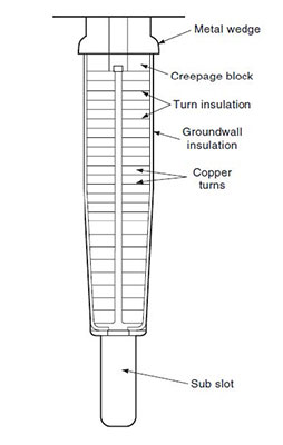
Figure 1. Cross-section of round rotor winding slot showing the insulation system components.
Failure of the turn insulation, even in multiple locations, does not necessarily result in a generator or synchronous motor shut down. Failed turn insulation leads to an increase in rotor vibration (due to unsymmetrical magnetic fields and unsymmetrical rotor heating/expansion), but as long as the vibration is tolerable, the generator can continue to operate. However, if more and more turn faults occur, it is likely that a ground fault or a “high bearing vibration” trip will eventually result.
A ground insulation fault in a synchronous machine rotor winding is usually considered important enough that the machine is shut down. Ground faults may be due to direct aging of the ground insulation, or cumulative action of an increasing number of turn faults.
The main testing and monitoring systems for rotor windings in use today detect the presence, number and location of turn faults. If the number of turn faults is increasing over time, then maintenance of the rotor winding is prudent to avoid a ground fault or a trip due to bearing vibration.
2.2 STATOR WINDINGS
Modern stator windings in motors and generators rated 3.3 kV or more are manufactured from individual form wound coils or bars [2]. Most machines rated less than about 50 MVA use multi-turn coils (Figure 2), whereas generators rated above 50 MVA tend to use bars (half turn coils). In form wound coils there is both turn insulation and ground insulation. Failure of either system will almost immediately result in an over-current that will trip a circuit breaker. Even a single turn insulation puncture will allow a very large circulating current to flow in the affected coil due to AC induction from the other coils. This high current will melt the copper conductors and adjacent ground insulation in a few seconds. Thus any monitoring system needs to be sensitive to the gradual deterioration of the turn insulation and ground insulation, rather than the occurrence of faults, since the first fault will trip the machine. Regrettably, there still seems to be no diagnostic test to evaluate the condition of the stator turn insulation. The available turn insulation tests just determine if the insulation is punctured or not. Bar windings do not contain turn insulation.
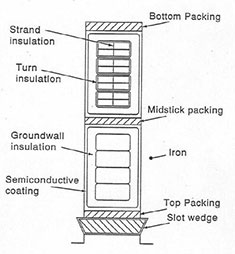
Figure 2. Cross-section of a stator slot showing two multiturn coil legs in the slot.
The turn insulation in modern stator windings rated 3.3 kV and above is usually made from a fiberglass and polyester tape, and/or mica paper tape [2]. The ground insulation is almost universally made from mica paper tapes bonded together with epoxy. In addition, in most stators rated 6 kV and above, there are partly conductive coatings on the surface of the coils and bars to prevent partial discharge [2].
There are a wide variety of degradation processes that will eventually lead to stator winding turn or ground insulation puncture [2]. These include:
- thermal deterioration caused by long time operation at high temperature;
- abrasion of the insulation due to coil and bar vibration induced by the magnetic fields;
- thermomechanical deterioration caused by rapid load changes;
- partial discharges due to inadequate design or manufacture which leaves air voids within the groundwall or insufficient space between coils in the endwinding (the part of the winding outside of the stator core);
- partly conductive contamination of the endwinding leading to electrical tracking.
These processes usually take from years to decades to cause failure. Note that failure can also be caused by metallic debris in the machine, or as a consequence of a severe operating event, such as connecting only two of the three phases to the power system, or out-of-step synchronization. Neither of these can be detected in advance by diagnostic tests or condition monitoring.
3 ROTOR TESTING AND MONITORING
Most of the off-line tests that are available to evaluate rotor winding insulation have been used for decades and only evolutionary progress has occurred. Since the rotor winding “rotates”, on-line monitoring continues to be a challenge. Thus, compared to stator windings, there are few on-line rotor winding insulation monitors.
3.1 OFF-LINE TESTING
The only off-line diagnostic test that evaluates the condition of the groundwall insulation continues to be the insulation resistance (IR) and polarization index (PI) test which is conducted with a megohmeter. The test method is discussed in IEEE 43. Except for automation of the test, the test is unchanged from when it was introduced many decades ago. Interpretation for rotor ground insulation is discussed in IEEE 43, and it remains essentially unchanged from the past. In addition, one can do a rotor winding overpotential (hipot) test on the ground insulation, but it seems this is rarely done [5].
There are a few more off-line tests for the rotor winding turn insulation. However, these just evaluate if a shorted turn(s) is already present. Formally these are not diagnostic tests, since none of these tests can assess how close to failure the turn insulation may be. The tests to detect shorted turns include:
- AC pole drop test in salient pole machines and the voltage drop test in round rotors.
- Recurrent surge oscillograph (RSO) test for round rotors.
These tests have been used for decades. More details are in [2].
3.2 TEMPERATURE MONITORING
Even though thermal stress is amongst the most important causes of rotor winding insulation failure, there has been little practical advancement in the ability to monitor the rotor winding insulation temperature in normal service. Today, as in the past, the rotor winding temperature sensor is usually the winding itself, where the resistance of the rotor winding can be monitored and calibrated for copper temperature change. This average temperature will not be indicative of the temperature of hot spots, for example where there are local blockages of cooling gas channels. It is the hot spot temperature that is the cause of thermal insulation aging.
Rotor hot spot monitoring is very difficult. One challenge is bringing the temperature signal off the rotor. Also, the very high rotational forces imply that the temperature sensors must be mechanically robust. Point temperature sensors for rotor windings have been developed for research purposes. These sensors tend to use a thermocouple, where the output voltage is converted to a digital signal and broadcast off the rotor using a radio frequency transmitter [6]. These sensors are point temperature sensors. Careful thought is needed for their placement. They are rarely employed in normal motor or generator applications.
An alternative method is to use thermal imaging of the rotor from a sensor based on the stator. Hotspots can therefore be mapped as the rotor turns. This type of monitoring is best for salient pole windings where the magnet wire or copper strips used on the rotor can be directly observed.
In addition, temperature-sensitive tagging compounds can be used to identify if certain rotor winding components have reached a specified temperature. These are described in more detail in Section 4.3.
3.3 MAGNETIC FLUX MONITORING
Magnetic flux monitoring to detect shorted turns is now widely used on turbine generator rotors. This test was first developed by Albright in the 1970s [7, 8]. More recently it has been made more flexible and has been extended to salient pole rotors [9]. As with the off-line rotor tests, flux monitoring is not a diagnostic test, but rather detects the presence (or not) of rotor winding shorted turns. If the number of shorted turns increases, there is a greater risk of a ground fault, and the bearing vibration levels may become unacceptable.
As originally applied to turbine generator round rotors, this monitoring system employed a ‘flux probe’ and a digital oscilloscope to record the measured signals from the probe. In the original method [7, 8], the flux probe was usually permanently installed within the air gap to measure the flux. The probe consists of a large number of turns of small diameter magnet wire on a bobbin, with the axis of the coil oriented in the radial direction. During machine operation, the flux from each rotor slot will induce a voltage in the flux probe, since the rotor is moving past the flux probe. Each peak of the voltage waveform represents the flux around one rotor slot. An interturn insulation fault in a coil reduces the peaks associated with the two slots containing the faulted coil, since there are less ampere-turns in the slots and thus less flux, reducing the voltage induced in the flux probe. The recorded waveform (Figure 3 above) is analyzed to locate the coil(s) and the slot(s) containing the faulted turn(s) and to indicate the number of turns faulted. This is usually done by comparing the induced voltage pattern from the coils around each magnetic pole. If there is a short in one coil in one pole, it will have less induced voltage than the similar coil around the other pole. To maximize sensitivity to shorted turns in all round rotor coils, the load has to be varied in steps from 0 to a little more than full load [2, 8, 10].
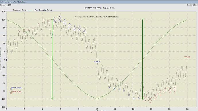
Figure 3. Voltage induced in a flux probe vs time (one AC cycle for a 2 pole machine) shown by the gray (faint) line. The leading coils of each pole are numbered. The light green (smooth quasi sinusoidal) line is the integrated flux density. The vertical dark green line is the location of Flux Density Zero Crossing.
In the past 10 years four main developments have occurred:
- The introduction of continuous on-line monitoring, as opposed to periodic on-line testing [9].
- The application of flux monitoring to salient pole machines such as hydrogenerators [9].
- The introduction of a printed circuit probe that can sometimes be retrofitted to a generator while the rotor is still within the machine, by gluing the probe to a stator tooth [9].
- New analysis algorithms and high resolution hardware which reduce the need to maneuver load over the full operating range of 0 MVA to full load to detect shorts in all round rotor coils [10].
4 STATOR WINDING MONITORING
Progress has been greatest in the assessment of stator winding insulation, perhaps because most machine insulation failures occur in the stator winding. In addition, most of the methods available for stator windings provide diagnostic information on how deteriorated the insulation is, and not just if the insulation has already failed. Over the past decade, only one new type of on-line monitor was introduced. Most advancements have been evolutionary in nature. On the other hand, several new tests have been introduced for off-line diagnostic testing.
4.1 OFF-LINE TESTING
There are several off-line diagnostic methods that have been used for decades to assess the condition of the stator winding ground insulation:
- Insulation resistance and polarization index tests (IEEE 43)
- Dissipation factor tip-up test (IEEE 286)
- Off-line partial discharge test (IEEE 1434 and IEC 60034-27)
- Blackout test (IEEE 1799)
The recent improvements in these tests have been primarily due to hardware improvements. For example, megometers to measure the IR and PI are available for voltages up to 10 kV now, and generally can accurately measure up to tens of Gigaohms. The dissipation-factor tip-up test is now often performed by measuring the precise phase angle between the voltage and current waveforms using a reference capacitor that is optically coupled to the measurement instrumentation. Similarly, almost all PD detectors used for off-line PD measurements perform a digital phase-resolved PD measurement, where the patterns measured with respect to the AC phase angle may indicate the root cause of any insulation deterioration [11]. A better alternative to blackout testing to detect surface PD is now possible due to the availability of inexpensive ultraviolet imaging devices.
In addition to these conventional tests, researchers have been investigating the use of polarization/depolarization current (PDC) measurement as well as dielectric spectroscopy, which in principle are related to one another. The PDC test has been championed separately by Bhumiwat and David [12, 13]. This test, which is a variation of the IR/PI test, connects a moderately high DC voltage (around 5 kV) to the stator winding and accurately measures the charging current. After 10 to 20 minutes, the DC supply is removed and the winding is shorted to ground while measuring the discharging current for the same amount of time. The discharging current is then inverted and displayed on the same time axis as the charging current. Ideally the two lines will overlap. If they do not, it may be an indication of stator winding insulation contamination, uncured epoxy, or perhaps delamination of the insulation due to thermal aging.
Dielectric spectroscopy is the frequency domain version of the time domain PDC method. It is usually performed over the frequency range of 1 mHz to about 1 kHz, using a specially designed dissipation factor instrument [14]. Results to date have been sporadic, and tend to be on bars/coils rather than on complete windings. Theoretically, it should provide the same information as the PDC test.
A diagnostic test that can detect degradation of the stator winding turn insulation before failure has not been developed yet. The stator turn insulation tests that are available, such as the surge voltage test and the impedance test [2], can only detect if a turn short has already occurred.
4.2 CONVENTIONAL TEMPERATURE MONITORING
Thermal aging is one of the most common stator insulation deterioration processes, at least for air-cooled machines. Thus it is no surprise that stator winding temperature monitoring is widely used on stators rated 3.3 kV and above. RTDs and thermocouples have long been employed to measure the temperature of the winding insulation in the stator slot. However, until the past decade, most of these sensors were used to alarm operations personnel of major temperature excursions which warrant immediate attention. Recently there has been a huge reduction in the cost of temperature scanners that can monitor hundreds of temperature sensors. Also, modern software has been developed to detect even small excursions in temperature (corrected for load and ambient temperatures). Thus it is now cost effective to monitor for situations that could lead to the more rapid thermal deterioration of the insulation before catastrophic failure results. Thus shorted strands, local blockages or restrictions in cooling gas flow, extensive contamination of the windings and the core (which increases the thermal impedance and thus the temperature) can be detected in normal operation of the motor or generator [15].
4.3 “CONDITION MONITORS” AND TAGGING COMPOUNDS
Condition monitors and tagging compounds are another way of directly detecting insulation that is overheated, in both the stator and rotor windings. The first condition monitors were developed in the 1970s specifically to detect burning of the stator core lamination insulation in large hydrogen-cooled turbine generators. When overheating occurs inside the generator, any organic material affected, such as epoxy insulation, will thermally decompose to produce a great number of particulates (‘smoke’) the size of condensation nuclei (0.001 to 0.1 m). These are readily detected by a device called a generator condition monitor (GCM) since, under normal operation, particulates of this size should not be present in the hydrogen gas [16]. The GCM is able to detect burning organic material, whether on the rotor, stator winding or in the stator core, using the same principle as a household smoke detector.
The introduction of large air-cooled gas turbine generators, and the ever-larger hydrogenerators, has caused the re-engineering of the GCM for application in air-cooled machines [17]. The device is installed in the air-cooling system in a totally enclosed fan cooled machine, and a cloud chamber principle is used to detect the particulates.
Most insulation will not produce particulates (smoke) until they are at very high temperatures. In rotor and stator windings, if the groundwall insulation is at such a high temperature, it is likely that a ground fault will follow within minutes or hours. This is in contrast to stator cores, where the core lamination insulation can burn locally, but this does not imply that the machine will fail even within the next few years. Consequently, GCMs are usually not able to give much warning of overheating problems in the rotor and stator windings.
To address this limitation, tagging compounds were developed in the 1970s to be used in conjunction with GCMs [18]. Tagging compounds are applied as a paint to any desired surface in a hydrogen-cooled or totally enclosed air-cooled machine. Usually several different types of tagging compounds will be used in the same machine. When the surface heats up to a specified temperature, particles with unique chemical signatures are released into the cooling air or hydrogen. These particles will normally trigger the GCM alarm, since they have the same particle size as smoke. Some types of GCMs have the ability to divert the hydrogen or air stream containing particles through a filter, which can trap the particles for later analysis. When convenient, the filters are removed from the GCM, and the particles undergo chemical analysis, either with a gas chromatograph (GC), or a mass spectrometer (MS). The idea is that if these chemicals are detected on the filter, the surface that was painted with them reached the temperature at which the chemicals are released. Thus, not only can the temperature of the winding be measured, but the location of the hot spot can be determined, as long as one knows where each type of tagging compound was painted. The tagging compounds are usually chlorine compounds encapsulated within microspheres.
4.4 OZONE MONITORING
Ozone, or O3, is a gas that is a by-product of partial discharge, that can occur in air–cooled machines rated 3.3 kV or more. Ozone results when PD is occurring on the surface of stator coils/bars due to loose windings, semiconductive or grading coating deterioration, and insufficient coil spacing in the endwinding. Monitoring ozone is thus a means of detecting if surface PD is occurring. In the past, the ozone was detected by chemical means. However, electronic ozone monitors using metal oxide semiconductor field effect transistor (MOSFET) sensors are now widely and inexpensively available, since they were developed for pollution monitoring. The ozone sensors are mounted within the machine enclosure and the measuring instrument can be located remote from the machine [19].
4.5 PARTIAL DISCHARGE MONITORING
Partial discharges are a symptom (and sometimes a cause) of many stator winding insulation problems. PD monitoring has become widespread for stator winding insulation rated 6 kV and above over the past 20 years, with over 50% of large North American utility generators employing this technology [20]. Every partial discharge creates a small current pulse that will propagate throughout the stator winding. Since the pulses are typically only a few nanoseconds in duration, using a Fourier transform, each pulse creates frequencies from DC to several hundred megahertz [21]. These electrical pulses are detected and processed in several different ways by the numerous PD monitoring systems available.
In virtually all systems, the following elements are found:
- Sensors, such as antennae, high voltage capacitors on the machine terminals, and/or RF current transformers at the machine neutral or on surge capacitor grounds are needed to detect the PD current pulses.
- Electronics to convert the pulse signals from analog form to a digital form. By far the most common approach is to use pulse magnitude analyzers. More recently, pulse phase analyzers also digitally record where the PD pulses occur with respect to the power frequency ac cycle.
- Signal processing techniques to reduce the information to manageable quantities and/or help discriminate PD signals in the winding from electrical noise to ensure more reliable interpretation.
The most popular sensors used in on-line PD monitoring are high voltage capacitors installed on each phase terminal [22, 23]. The capacitor blocks the 50 or 60 Hz high voltage, while being a low impedance path for the high frequency PD pulses. The sensor capacitance is typically between 80 pF and 9 nF. Various forms of antennae installed within the motor or generator enclosure are also employed to detect PD on-line. The most widely employed ‘antenna’ is called the stator slot coupler (SSC). It is a strip line directional coupling antenna that is usually installed under the wedge in a stator slot containing coils or bars operating at high voltage [22]. Alternatively, microwave horn antennae or patch antennae are sometimes used [24, 25]. In general, on-line PD detection systems tend to operate in the HF (3-30 MHz), VHF (30-300 MHz) and UHF (300-3000 MHz) frequency ranges, in contrast to the off-line PD system (Section 4.1) which is usually in the LF (< 3 MHz) range. The advantage of the LF range is its greater sensitivity to PD throughout the stator winding, whereas the higher frequencies are less sensitive to PD remote from the sensor. However, the HF and above ranges offer greater suppression of noise, which can cause false indications in on-line monitoring (see IEEE 1434 or IEC 60034-27-2.)
Three predominate means have been developed to separate the PD from the interference, beyond simple filtering. One requires the installation of at least two sensors per phase, and measuring the relative time of arrival [22, 26]. This is widely used on hydrogenerators and air-cooled turbine generators. The other is to look at each pulse and determine if the pulse shape is characteristic of PD or noise [22]. Both of these noise separation methods require the system to operate in the VHF or UHF frequency range to measure PD pulses with a pulse arrival time to within a few nanoseconds and to capture the pulse shape with reasonable fidelity. A software implementation of the pulse shape analysis method is called a time-frequency map [27]. The final means is to use pattern recognition techniques, to emulate the ability of a human expert to separate visually PD from interference. Usually advanced statistical analysis or neural networks are employed [26, 28, 29].
In the past 10 years, the periodic measurement of PD during normal motor and generator operation has been replaced with continuous monitoring of the PD, using dedicated instrumentation which makes the PD data continuously available to the plant or remote computers. Systems are available from many vendors.
Significant progress has been made in the area of PD interpretation. Interpreting stator winding PD is fundamentally different than PD interpretation from other types of HV equipment, since PD is almost always present in stator windings 3.3 kV and above. To some extent, PD can be tolerated indefinitely because of the presence of mica in the insulation system. In other types of equipment, any PD at operating voltage will eventually lead to failure, and thus one makes sure no PD is occurring in-service. The question regarding rotating machine PD is what level can be withstood before one has concern about the viability of the insulation. The rotating machine PD standards (IEEE 1434 and IEC 60034-27-2) do not address this. In the past decade one organization has proposed limits based on correlating PD levels with actual visual inspection of the windings [30, 31]
The trend in PD magnitude over time has long been the primary method of determining if insulation maintenance is needed. However, there is now recognition that in severely deteriorated insulation, the PD will level off eventually. That is, PD will not increase indefinitely until the insulation fails [20].
As with PD in other types of equipment, the pattern of the PD with respect to the AC cycle may provide clues about the root cause of the PD. Researchers at IREQ have performed extensive experiments where they simulate various PD processes and observe the associated PD pattern [32]. This approach to determining the failure processes occurring in a winding seems to be effective as long as there is a single dominant failure process [20]. Of course research is on-going to find reliable ways of automatically determining the failure process from the PD patterns. Neural networks, time-frequency maps, statistical analysis and fractal analysis are popular [20, 26-29]. However, much work remains to validate the pattern recognition approaches before motor and generator owners will adopt these methods.
4.6 ENDWINDING VIBRATION MONITORING
Stator endwinding vibration is an important cause of turbine generator failure, and in recent years this failure process seems to be becoming even more common as machine manufacturers reduce cost by reducing the labor and material involved in creating the support structure [33, 34]. The endwindings in large 2-pole machines are particularly prone to vibration due to the length of the endwindings. The main driving force causing the vibration is the power frequency current in the stator bars which creates twice power frequency magnetic forces in the radial and tangential directions [2, 33, 34].
Endwinding vibration monitors have been developed to directly measure the presence of endwinding vibration. Vibration is detected by accelerometers, which produce an electrical output that is proportional to the magnitude of the acceleration the sensor sees. With manipulation, this signal can also be calibrated in terms of vibration velocity or displacement. Most accelerometers are made from piezoelectric crystals that are enclosed in a metallic shell. Since these conventional accelerometers are metallic and operate near ground potential, they cannot be permanently installed in the endwinding of the stator. If they were, with normal pollution, it is likely that the grounded accelerometer would eventually initiate an electrical tracking failure.
Over the past 20 years, fiber optic accelerometers have been developed which will not compromise the electrical integrity of a winding, since they contain no metallic parts.
Several different optical accelerometers have been developed [34-36]. Westinghouse introduced the first in the early 1980s, although this sensor could only detect 120 Hz vibration [35]. After relatively conventional signal processing, a plant computer can continuously monitor the vibration magnitude.
As yet there are no standards for endwinding vibration monitoring, and thus no accepted limits for what level of vibration is acceptable. However, Reference [2] does propose a limit in terms of displacement, but with little justification.
4.7 ON-LINE LEAKAGE CURRENT MONITORING
All the techniques described above for on-line stator winding monitoring have been in use for decades. Most of the recent research has revolved around evolutionary improvements. On-line leakage current monitoring is a completely new method developed by GE in the past decade to detect winding contamination by partly conductive pollution [37]. However, widespread application has yet to occur.
Figure 4 shows how the leakage current to the stator winding can be isolated from the major load current to or from a stator. The method requires a high sensitivity current transformer (HSCT) to be placed around the combined high voltage and neutral phase leads of a wye-connected stator winding. The phase-end current and the neutral current on a single phase will consist of the “load current” and the capacitive current. If the leakage current is zero, the phase and neutral currents will be identical and the HSCT output in Figure 4 will be zero. However, if the CT is very accurate and sensitive, a net current difference will occur which is equal to the leakage current through the insulation. This difference current is very tiny compared to the normal load current – perhaps in the range of 10-3. Thus the CT must be very accurate and not be sensitive to the lead placement. Capacitance and dissipation factor can then be calculated from the voltage as well as the in-phase and quadrature difference current, respectively [37].
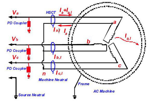
Figure 4. On-line measurement of the leakage current using a very sensitive CT [37].
5 CONCLUSION
In recent years there has been good progress in improving established tests and monitors that can warn of developing insulation system problems in rotor and stator windings. These advances in technology have made such systems easier to use, more reliable in predicting insulation condition and thus have lead to widespread application, at least in North America. In addition, research has begun into the application of newer methods such as PDC, dielectric spectroscopy and on-line leakage current. These latter methods have yet to be fully accepted by machine owners.
REFERENCES
[1] G.C. Stone, “Advancements during the Past Quarter Century in On-Line Monitoring of Motor and Generator Winding Insulation”, IEEE Trans. Dielectr. Electr. Insul., Vol. 9, No. 5, pp. 746-751, 2002.
[2] G.C. Stone, I. Culbert, H. Dhirani, and A. Boulter, Electrcial Insulation for Rotating Machines, Wiley-IEEE Press, 2004.
[3] P. Tavner, L. Ran, J. Penman, and H.G. Sedding, Condition Monitoring of Rotating Electrical Machines, Institution of Engineering and Technology, Power and Energy Series, UK, 2008.
[4] G.C. Stone and I. Culbert, “Prediction of stator winding remaining life from diagnostic measurements”, IEEE Int’l. Sympos. Electr. Insul., pp.
1- 4, 2010.
[5] R.Ilie and G.C. Stone, “Turbine Generator Rotor and Stator Hipot Testing”, IEEE Electr. Insul. Mag., Vol. 28, No. 2, pp. 29-37, 2012.
[6] J. Dymond, R. Ong, and N. Stranges, “Instrumentation, Testing and Analysis of Electric Machine Rotor Steady State Heating,” in Proc IEEE Petroleum and Chemical Industry Conf., Toronto, pp. 297-303, 2001.
[7] D.R. Albright, “Interturn Short-Circuit Detector for Turbine-Generator Rotor Windings”, IEEE Trans. Power App. Syst., Vol. 90, pp. 478-483, 1971.
[8] D.R. Albright, D.J. Albright, and J.D. Albright, “Flux probes provide on-line detection of generator shorted turns”. Power Engineering, pp. 28-32, 1999.
[9] G.C. Stone, M. Sasic, J. Stein, and C. Stinson, “Using Magnetic Flux Monitoring to Detect Synchronous Machine Rotor Winding Shorts”, IEEE Petrochemical Industry Conf., pp. 1-7, 2011.
[10] M. Sasic, B. Lloyd, and A. Elez, “Finite Element Analysis of Turbine Generator Rotor Winding Shorted Turns”, IEEE Trans. Energy Conversion, Vol. 27, No. 4, pp. 930-937, 2012.
[11] C. Hudon and M. Belec, “Partial Discharge Signal Interpretation for Generator Diagnostics”, IEEE Trans. Dielectr. Electr. Insul., Vol. 12, No. 2, pp. 297-319, 2005.
[12] S. Bhumiwat, “On-Site Non Destructive Dielectric Response Diagnosis of Rotating machines”, IEEE Trans. Dielectr. Electr. Insul., Vol. 17, No. 5, pp. 1453-1460, 2010.
[13] E. David, R. Soltani, and L. Lamarre, “PDC Measurements to Assess Machine Insulation”, IEEE Trans. Dielectr. Electr. Insul., Vol. 17, No. 5, pp. 1461-1469, 2010.
14] M. Farahani, H. Borsi, and E. Gockenbach, “Dielectric Response Studies on Insulating Systems of Rotating Machines”, IEEE Trans. Dielectr. Electr. Insul., Vol. 13, No. 2, pp. 383-393, 2006.
[15] B.A. Lloyd and G.C. Stone “On-Line Condition Monitoring To Improve Generator Availability”, EPRI Steam Turbine/Generator Workshop, Baltimore, 2001.
[16] J.M. Braun and G. Brown, “Operational Performance of Generator Condition Monitors”, IEEE Trans Energy Conversion, Vol. 5, No. 2, pp.
344- 349, 1990.
[17] S. Kilmartin, “Prefault Monitor for Air-Cooled Generators”, EPRI Utility Motor and Generator Predictive Maintenance Conf., San Francisco, 1993.
[18] S. Kilmartin, “Gen Tags”, Australian Major Component Reliability and Materials Group Meeting, Queensland, Australia, 2012.
[19] M. Belec, S. Li, D.N. Nguyen, L. Lepine, C. Guddemi, D. Lessard-Deziel, T. Schwartz, and L. Lamarre, “Investigation and Diagnosis of 184 MVA Air Cooled Generator Heavily Affected by Slot PD activity”, IEEE Electr. Insul. Conf., pp. 85-90, 2007.
[20] G.C. Stone, “A Perspective on On-Line PD Monitoring for Assessment of the Condition of Rotating Machine Stator Winding Insulation”, IEEE Electr. Insul. Mag., Vol. 28, No. 5, pp. 8-13, 2012.
[21] S.A. Boggs and G.C. Stone, “Fundamental Limitations in the Measurement of Corona and Partial Discharge”, IEEE Trans. Electr. Insul., Vol. 17, No. 2, pp.143-150, 1982.
[22] S.R. Campbell, G.C. Stone, H.G. Sedding, G.S. Klempner, W. McDermid, and R.G. Bussey, “Practical On-Line Partial Discharge Test for Turbine Generators and Motors”, IEEE Trans. Energy Conversion, Vol. 14, No. 6, pp. 281-287, 1994.
[23] T.E. Laird, J. Fiaux, and T. Bertheau, “Periodic on-line partial discharge measurements on air cooled and gas cooled generators of similar design”, IEEE Electr. Insul. Conf., pp. 101-105, 1997.
[24] H. Muto, Y. Kaneda, H. Aoki, and O. Hamamoto, “On-line PD monitoring system for rotating machines using narrow band detection of EM wave in GHz range”, IEEE Int’l. Conf. Condition Monitoring and Diagnosis, Beijing, China, pp. 1093-1096, 2008.
[25] A. Cavallini, G.C. Montanari, and A. Salsi, “Characterization of Patch Antennae for PD Detection in Power Cables”, IEEE Conf. Electr. Insul. Dielectr. Phenomena, pp. 179-182, 2007.
[26] G.C. Stone, “Partial Discharge Diagnostics and Electrical Equipment Insulation Condition Assessment”, IEEE Trans. Dielectr. Electr. Insul., Vol. 12, No. 5, pp. 891-904, 2005.
[27] A. Cavallini, M. Conti, A. Contin, G.C. Montanari, and F. Puletti, “A new algorithm for the identification of defects generating partial discharges in rotating machines”, IEEE Int’l. Sympos. Electr. Insul., pp. 204-207, 2004.
[28] E. Gulski and A. Krivda, “Neural Networks as a Tool for Recognition of Partial Discharges”, IEEE Trans. Electr. Insul., Vol. 28, No. 6, pp. 984-1001, 1993.
[29] A. Contin, M. Cacciari, and G.C. Montanari, “Use of a Mixed Weibull Distribution for the Identification of PD Phenomena”, IEEE Trans. Dielectr. Electr. Insul., Vol. 2, No. 4, pp. 614-627, 1995.
[30] V. Warren, G.C. Stone, and M. Fenger, “Advancements in Partial Discharge Analysis to Diagnose Stator Winding Problems”, IEEE Int’l. Sympos. Electr. Insul., pp. 497-500, 2000.
[31] C. Maughan, “Partial discharge – a valuable stator winding evaluation tool”, IEEE Int’l. Sympos. Electr. Insul., pp. 388-391, 2006.
[32] C. Hudon and M. Belec, “Partial discharge signal interpretation for generator diagnostics”, IEEE Trans. Dielectr. Electr. Insul., Vol. 12, No. 2, pp 297-319, 2005.
33] B. Gott, “Electromagnetic Forces in Stator Windings”, EPRI Turbine Generator Users Group Meeting, Albany NY, 2011.
[34] C. Maughan, “Vibration detection instrumentation for turbine-generator stator endwindings”, IEEE Electr. Insul. Conf., pp. 173-177, 2009.
[35] M. Twerdochlib, R.C. Miller, T.A. Lemak, R.L. Osborne, C.C. Repplier, D.R. Morrison, and D.J. Boomgaard, “Two Recent Developments in Monitors for Large Turbine generators”, IEEE Trans. Energy Conversion, Vol. 3, No. 3, pp. 653-659,1988.
[36] M. Sasic, H. Jiang, and G.C. Stone, “Requirements for Fiber Optic Sensors for Endwinding Vibration Monitoring”, IEEE Condition Monitoring and Diagnostics Conf., pp. 118-121, 2012.
[37] K. Younsi, P. Neti, M. Shah, J.Y. Zhou, J. Krahn, K. Weeber, and
C. D. Whitfield, “On-Line Capacitance and Dissipation Factor Monitoring of AC Stator Insulation”, IEEE Trans. Dielectr. Electr. Insul., Vol. 17, No. 5, pp. 1441-1452, 2010.
G.C. Stone (M’75-F’90) has a Ph.D. degree in electrical engineering from the University of Waterloo, Canada. From 1975 to 1990 he worked at the Research Division of Ontario Hydro. Since 1990 he has been working at Iris Power – Qualitrol as a Dielectrics Engineer. He has published over 200 papers in the rotating machine insulation field and has been active in writing both IEEE and IEC standards.