
IEEE 2016 International Conference on Condition Monitoring and Diagnosis – Xi’an – China
Abstract – There seems to be an increasing incidence of significant surface partial discharges (PD) in stator windings rated 6 kV and above. This surface PD causes bright white deposits on the stator coils, and is usually caused by poorly-made or poorly-applied partly-conductive and silicon carbide coatings. The problem is even more likely if the winding is connected to a voltage source-pulse width modulated inverter used in variable speed drives. If uncorrected, this surface PD leads to high ozone levels within the machine which degrades most metallic and organic components within the motor or generator enclosure. Eventually, a stator ground fault or rotor failure may occur. This paper reviews the mechanisms that may lead to surface PD in stator windings and discusses how PD can be detected using visual examination and ultraviolet imaging, as well as using condition monitoring tools such as electronic ozone monitors and on-line partial discharge measurements.
Keywords – partial discharge; ozone; stator windings
I. INTRODUCTION
Almost all motor and generator stator windings rated 6 kV and above have coatings on the surface of the coils or bars to suppress the occurrence of partial discharges (PD) on coils or bars operating at high voltage. In the stator core slot area of the coil/bar, and for a few centimeters outside of it, the coating is usually a graphite-loaded paint or tape that is referred to as the semiconductive or semicon coating. It is also called the conductive, outer corona protection (OCP), or PD suppression coating. The semicon coating has a surface area resistance of a few hundred to a few thousand ohms per square. It prevents the build–up of any voltage between the surface of the coil and the stator core, and thus prevents surface PD [1]. There is a different surface coating that extends from the end of the semicon coating to about 5 to 20 cm into the endwinding area. This coating is often referred to as the stress relief coating, the endwinding corona protection (ECP), the semiconductive coating (which is confusing since the graphite coating is called the same thing by some), or the silicon carbide coating. In this paper we will refer to it as the silicon carbide coating, since that is the most common material used in its manufacture. The purpose of the silicon carbide coating is to linearize the axial electric field at the end of the semicon coating, which would otherwise be highly non-uniform and thus create PD at the ends of the semicon coating. Fig. 1 shows coils that have these two coatings.
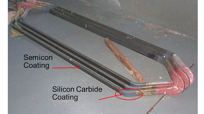
Fig. 1. Semicon and silicon carbide coatings on stator coils.
These two stress relief coatings can age and become non-functional over time. When they do, PD will occur on the line-end coils/bars since the coatings have lost their effectiveness to suppress the PD. The high energy electrons within each partial discharge will sometimes then collide with oxygen molecules in the air, creating O3 (ozone). The combination of PD and ozone may eventually lead to stator or rotor failure, as described below. There is anecdotal evidence that severe aging of the stress relief coatings is becoming more common, perhaps due to designs that result in higher stator winding operating temperatures and higher insulation electric stress [2]. Machines operating at altitudes above 1000 m are also at more risk, due to the lower air pressure. In addition, more motors are being supplied from voltage source – pulse width modulated (VS-PWM) variable speed drives which have also been shown to increase the deterioration rate of the stress relief coatings [1, 3].
This paper gives a brief description of the failure processes of stress relief coatings in both conventional stator windings and windings connected to a VS-PWM inverter. The effects of these failure processes on machine operation are then described. Finally, methods to detect when the deterioration is occurring, and thus when maintenance is needed, are discussed.
II. STRESS RELIEF COATING DETERIORATION PROCESS
A. Conventional Windings
The root cause of semicon coating deterioration is poor manufacturing procedures – most commonly when the semicon surface resistance is too high in localized areas. This is probably because the graphite particle density is too low in these areas. If a bar/coil with a locally high coating resistance is connected to the phase terminal, then capacitive currents flow from the copper conductors within the bar/coil, through the groundwall insulation, to the stator core via the semicon coating. Since the coating is not in direct contact with the core on its top and bottom edges (i.e., the narrow edges in the coil/bar cross-section) and at the ventilation ducts, some of the capacitive current must flow parallel to the bar/coil surface. Small I2R losses occur where the current is flowing laterally, heating the coating at these localized spots, especially if the semicon resistance is too high. This local heating, added to the general winding temperature, can lead to oxidation of the semicon coating, which further increases the semicon coating resistance, accelerating the mechanism. If the coating has very high (or infinite) resistance even in a small spot less than 1 cm in diameter, PD will occur in the line-end coils/bars. Quality control testing during manufacture to measure the resistance of the semicon over a significant portion of the coating on the coil/bar can prevent this mechanism. This process is most likely to occur with painted semicon coatings.
The semicon coating may also degrade if there is a poor bond between the coating and the underlying groundwall insulation. At these locations there may be a delamination or a cloud of microvoids, where tiny partial discharges may occur in the line-end coils/bars. These discharges attack the semicon, changing its resistance from a few hundred ohms to an infinite resistance. Experience shows this mechanism is most likely when the coating is made with partly-conductive tapes applied over the groundwall insulation.
B. VS-PWM Drives
Even semicon coatings in well-made windings, rated 3 kV and above, can degrade if the winding is connected to a VS-PWM inverter. The small capacitive current that flows through the semicon, especially outside of the stator core, is proportional to the frequency of the current. In VS-PWM drives, the voltage from the invertor is switching at up to 2000 Hz, rather than 50 or 60 Hz, so the frequency is 33 to 40 times higher than for a conventional machine. In addition, the risetime of the voltage impulses from the drive is typically 500-1000 ns, which corresponds to a Fourier frequency of about 1 MHz. This results in a dramatically higher current through the semicon, a higher I2R loss, and thus a much higher temperature at the coatings, which makes the coating resistance even higher [3]. Eventually PD occurs, destroying the coating.
C. Interface between the Semicon and the Silicon Carbide Coatings
The silicon carbide coating overlaps the semicon coating at both ends of a coil/bar (Fig. 1). In some cases, the electrical connection between the semicon and the silicon carbide coating has too high a resistance. This may be because either the graphite content in the semicon is too low, the silicon carbide particle density is too low, or the overlap area is insufficient to handle the current. The capacitive currents flowing through this high resistance electrical connection can lead to a local high temperature, which further increases the temperature. Eventually, thermal runaway occurs at the connection, which results in the silicon carbide coating becoming electrically disconnected from the ground, leading to PD across the surface of the insulation.
D. Effect on Machines
Once the semicon or the semicon/silicon carbide interface starts degrading, surface PD occurs. In air-cooled machines, the PD will create ozone (O3). Ozone is a very chemically reactive gas that combines with nitrogen and humidity in air, creating nitric acid (HNO3). The nitric acid attacks the adjacent semicon and silicon carbide coatings – which expands the area of damaged coatings. Figs. 2 to 4 show examples of degraded coatings.
Surface PD will also attack the epoxy in the groundwall insulation. A hole (electrical treeing) may eventually bore through the groundwall, causing a ground fault. However, since mica-based groundwall insulation is very PD resistant, it may take 15 to 20 years to cause failure.

Fig. 2. Example of the top of a motor stator coil where the semicon was poorly made and has turned white from its normal black color due to the action of ozone produced by the PD. This GVPI stator is only partially wedged. The photo was taken via a borescope with the rotor in situ.
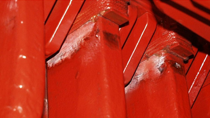
Fig. 3. Surface PD damaged the semicon coatings at the slot end on a 13.8 kV generator stator.
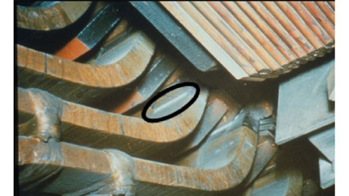
Fig. 4. Surface PD at the overlap between the semicon and the silicon carbide coating (circled) in a 13.8 kV hydrogenerator
In fact, it seems that other components are more likely to cause failure before the PD acting on the groundwall insulation causes a ground fault. In air-cooled machines, the nitric acid chemically attacks many different materials including the rubbers and metals. Thus, in machines that use air-to-water heat exchangers, the nitric acid has caused pinholes in the thin metal used in the heat exchangers, and the resulting water leaks have led to stator winding flashovers. Problems have also occurred in bearings leading to high vibration caused by degradation of the lubricating oil or grease due to the chemical reaction with nitric acid. Finally, the metal in highly stressed 2- and 4-pole rotors has cracked due to stress corrosion. For example, stainless steel retaining rings have cracked and detached from the rotor in some 4-pole induction motors due to decades-long exposure to ozone/nitric acid. Similar cracks have also occurred in the rotor windings of high speed synchronous motors.
III. METHODS TO DETECT STRESS RELIEF COATING DETERIORATION
The best way to prevent such problems is to have adequate quality control testing during manufacture. This involves measuring the resistance of the semicon and silicon carbide coatings. After manufacture, the coils or bars can be energized to rated line-to-ground voltage and examined with an ultraviolet imaging device to detect any surface PD from the defective coatings [4].
Once the machine has seen operation, there are two main methods to monitor the condition of the stress relief coatings during normal operation of the motor or generator:
• On-line PD monitoring
• Ozone monitoring
A. On-Line PD Monitoring
On-line PD monitoring using permanently installed PD sensors has been widely applied to machines rated 6 kV and above for over 25 years. The most common PD sensing method uses 80 pF capacitors mounted on each phase at the machine terminals as PD sensors [1, 5, 6]. Since the machines are connected to the power system where there may be considerable electrical noise, provisions are needed to separate the stator winding PD from all other pulse activity [5, 6]. The PD caused by deterioration of the stress relief coatings is driven by the phase to ground voltage, and thus the negative PD usually occurs between 0 and 90° of the ac cycle, while the positive PD occurs between 180 and 270° of the ac cycle. It is also well-known that the positive PD (i.e. the PD occurring from 180° to 270° of the ac cycle) tends to be higher than the negative PD [1, 6], although there are counter examples to this.
Fig. 5 shows the phase resolved PD plot for a large 13.2 kV motor with a global VPI stator winding. The PD was measured during normal operation of the motor with 80 pF sensors and a TGA-B™ on-line PD instrument. This plot shows the strong positive PD predominance and phase position typically associated with stress relief coating discharge. The positive and negative peak PD magnitude (Qm as defined in IEC 60034-27-2) is +931 mV and –451 mV. In comparison to the most recent version of a large PD database [5], the PD in this motor is higher than 95% of other similar motors – indicating very high PD activity. This conclusion was verified by a visual inspection of the stator, which showed widespread deterioration of the semicon coatings, and obvious signs of chemical attack by nitric acid throughout the motor enclosure. This motor has been operating for over 20 years, and the high PD is likely to have been occurring since shortly after going into operation. The motor has experienced heat exchanger water leaks, indicating a long term exposure to ozone and nitric acid.
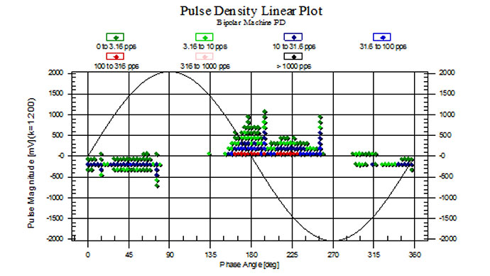
Fig. 5. Recent phase-resolved PD activity from a large 13.2 kV motor with visually confirmed deterioration of the semicon coatings similar to that shown in Fig. 2. The vertical scale is the positive and negative PD magnitude, the horizontal scale is the phase angle of the 60 Hz ac cycle, and the colour of the dots indicates the PD pulse repetition rate.
B. Ozone Monitoring
Surface PD from stress relief coating deterioration also generates relatively high concentrations of ozone. There are many electronic ozone monitors available, since such devices are also used for atmospheric pollution monitoring. These monitors use a MOSFET semiconductor device to detect the ozone gas. If the machine is open ventilated (often the case in smaller hydrogenerators), the MOSFET sensor is placed by the exhaust air from the machine. For totally-enclosed motors and generators, a hole is drilled in the machine housing, and the sensor is placed within the enclosure, hopefully at a location where the cooling air blows past (i.e. not in a dead air pocket). Successful condition monitoring based on ozone measurements, requires very careful consideration of the placement of the sensors. As with on-line PD, the monitor can be used to periodically test many machines, or continuous monitoring can be performed on a single motor or generator.
Fig. 6 shows the ozone concentration in ppm over a 6 year period for the same motor discussed above where the surface PD was high. The concentration reached as high as 75 ppm. This is exceptionally high. Reference [1] suggests that a concentration of 1 ppm should be considered high, but this assumed open-ventilated machines. In totally-enclosed machines, the only way to consume the ozone that is always being created by the PD, is when it chemically reacts with other materials within the motor or generator. Thus, in totally enclosed machines, the ozone concentrations are much higher than in open-ventilated machines. It is also the reason that the ozone and nitric acid are more likely to cause water leaks and rotor stress corrosion cracking in totally-enclosed machines.
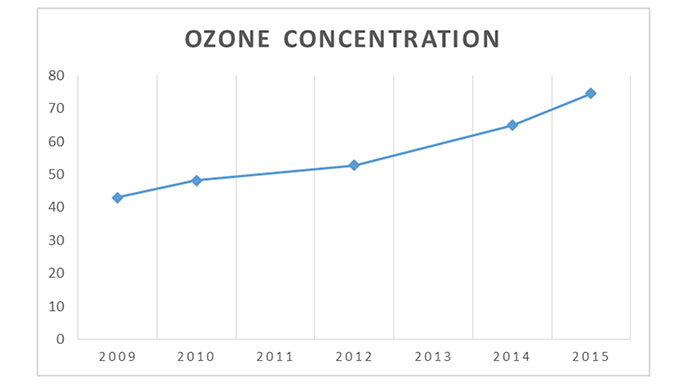
Fig. 6. Ozone concentration within the same motor as discussed in Fig. 5. The vertical scale is in parts per million of ozone.
IV. CONCLUSION
Degradation of the surface PD suppression coatings is an important failure process in air-cooled motors and generators. This problem is fundamentally caused by imperfect manufacturing of the stator coil or bars. However, it is more likely to occur in machines with higher stator winding temperatures, or machines designed to operate with the insulation at higher electric stress. The introduction of VS-PWM invertors accelerates the aging process due to the high frequency voltage impulses such invertors create.
There are two main methods of detecting the surface PD caused by deteriorated stress relief coatings: on-line PD monitoring and ozone monitoring. An example was presented confirming that such deterioration leads to high level PD and high concentrations of ozone. Although stator winding insulation failure may take decades, it seems the ozone and associated nitric acid may cause failure sooner due to rotor failure or heat exchanger water leaks.
REFERENCES
[1] G.C. Stone et al, Electrical Insulation for Rotating Machines, Wiley-IEEE Press, 2014
[2] G. Stone et al, “Motor and Generator Windings – Recent Problems Experienced”, IEEE Industry Applications Magazine, November 2011, pp 29-36.
[3] E. Sharifi, S. Jayaram, E. Cherney, “Analysis of Thermal Stress in Medium Voltage Motor Coils Under Repetitive Fast and High Frequency Pulses”, IEEE Trans DEI, 2010, pp 1378-1384.
[4] IEEE 1799-2012 – IEEE Recommended Practice for Quality Control Testing of External Discharges on Stator Coils, Bars, and Windings.
[5] G.C. Stone, V. Warren, “Objective Methods to Interpret Partial-Discharge Data on Rotating-Machine Stator Windings” IEEE Transactions on Industry Applications. Vol.42, No.1, January/February 2006, pp 195-200.
[6] IEC 60034-27-2-2012 Rotating electrical machines – Part 27-2: On-line partial discharge measurements on the stator winding insulation of rotating electrical machines.