
Deterioration Processes in Large Generator Stator Cores
According to Clyde Maughan, deservedly self ‐described as the best (living) expert on class B insulated turbo generators, and widely recognized as one of the best experts on all types of turbo generators, evaluation of the condition of a stator core is a major technical challenge. The stator core of a typical large (e.g. 500MW) turbo generator weighs 200 tonnes, is approximately 6m long, 2.6m in diameter and has a bore of 1.5m. The largest hydro generator cores are approximately 20 m in diameter and up to 3 m long. The stator core is built from a stack of some 200,000‐500,000 individual steel sheets or “laminations” each 0.3 to 0.5mm thick and coated on each side with a layer of electrical insulation to prevent current flow between them. Cores used to be built exclusively in the factory and then shipped to a power plant site. Due to shipping limitations, large hydro generator cores were usually manufactured and shipped in sections and assembled on site. To‐day, both turbo and hydro generator cores are frequently assembled on site, using individual steel sheets, or in some turbo generators, using preassembled core sections.
Although the stator core is one of the most reliable parts of a rotating machine, and multiple stator winding re‐winds are possible on the same core, various deterioration process may affect the stator core, and particularly the lamination insula‐tion. These processes can be divided into thermal, mechanical and electrical. The root causes of core insulation thermal degradation can be catagorized as general overheating, local overheating, and inappropriate stator winding burnout procedures during re‐wind. Although most cores built after 1970 are made of laminations insulated using non‐organic coatings rated 400 C and higher, both local and general overheating may damage the interlaminar insulation. General core overheating accidents are almost always caused by loss of cooling medium, such as failure of cooling water pumps in totally enclosed directly or indirectly water cooled machines, or partial or complete blockage of ventilation in air cooled machines. Local overheating is usually caused by design or manufacturing errors, or blockage of radial or axial cooling passages in the core. Due to the large core mass, local overheating is not likely to cause core looseness, but it could result in core and stator winding insulation damage. One of the critical deterioration mecha‐nisms actually does not take place during machine operation‐stator winding burnout is frequently used on smaller cores as an effective method to remove an old stator winding. If the core temperature radial or axial cooling passages in the core. Due to the large core mass, local overheating is not likely to cause core looseness, but it could result in core and stator winding insulation damage. One of the critical deterioration mechanisms actually does not take place during machine operation‐stator winding burnout is frequently used on smaller cores as an effective method to remove an old stator winding. If the core temperature exceed 350-400 C during the winding burnout, localized or general core damage is likely to happen. Therefore, it is good practice to perform core interlaminar insulation testing, using full excitation level LOOP test or EL CID test, before and after removal of the old winding.
Electrical degradation of stator core can be caused by operation of the core outside of its design parameters or stator winding failure. Underexcitation and overexcitation can result in high core temperatures in two different areas: the step iron and back of the core, respectively. The step iron at the two ends of the core is the most stressed part of the core, and failure of interlaminar insulation can lead to complete core meltdown. Each manufacturer specifies the time limit (in seconds) how long the core can be overexcited, and one minute at 25% higher than nominal excitation voltage, can result in core meltdown. This situation can occur during the synchronization of generator with the system, if rotational speed and excitation voltage are not properly controlled. The loss of insulation on the stator core through‐bolts (some core designs) and stator winding earth faults in core slots or at core edges, can cause melting of the core iron, requiring partial or complete core replacement, see Figure 1.
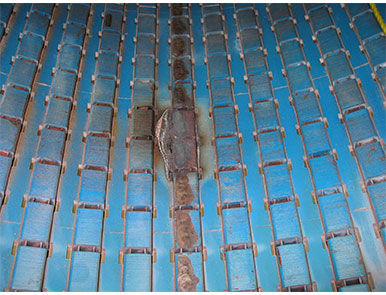
Figure 1. Stator winding fault resulting in core damage
Mechanical core degradation is mainly caused by the lack of compression of core lami‐nations, or movement of a core section in large machines (usually hydrogenerators) with seg‐mented core construction. Also, lose metallic components entering the air gap, may cause surface core damages, if attracted to the core, shortening the laminations. A lack of compression in the presence of large magnetic forces may create relative movement of core plates, and removal of lamination insulation by abrasion. This will result in creation of a conductive path and current flow between laminations lead‐ing to core damages. Cores made of multiple segments, (two, or more, up to six or eight) can experience the damage on core splits, due to movement of core sections, see Figure 2.
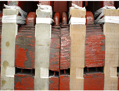
Figure 2. Core split damage
A couple of years ago, to assist in “a major technical challenge” of core evaluation, IEEE created new IEEE Working Group, P1719 working on a Guide for Evaluating Stator Cores of AC Electric Machines Rated 1MVA and Higher. The final version of this Guide is expected to be com‐pleted in 2015, and we are actively participating in this WG.