
Dissipation Factor Acceptance Criteria for Stator Winding Insulation
Dielectric dissipation factor testing, also known as tangent delta or power factor testing, is a measure of the dielectric losses in an insulation system. In the field of rotating machines, this technique is widely used as an appropriate means of assessing the quality of new and also aged stator winding insulation. The method is useful for assessing the uniform quality of manufacturing and the dielectric behavior of the insulation as a whole. For aged stator windings, the dielectric dissipation factor provides information about insulation condition. Certain deterioration processes, such as thermal aging or moisture absorption, will increase dielectric losses. Thus, trending of the dielectric loss over time may be employed as an indication of certain types of insulation problems.
The main principle is to measure the dielectric dissipation factor over a range of voltages and to derive different characteristic dielectric loss parameters as a basis for the evaluation. Typically, practitioners of dissipation factor measurements have used three basic parameters as a means to assess insulation condition.
- The absolute dissipation factor value at a prescribed voltage, usually the rated phase-to-phase or phase-to-ground voltage.
- The incremental change in dissipation factor as the voltage is raised in prescribed increments.
- The change in dissipation factor as the voltage is increased from prescribed minimum to maximum voltages.
This latter parameter is widely known as the dissipation factor tip-up and has been considered by many to be the key value providing some insight into insulation condition. The test methods are described in IEEE 286 and the old
IEC 60894. Empirical limits of these three parameters, verified in practice, may be used as a basis for evaluating the quality of stator winding insulation systems in manufacturing.
Until recently, the limits applied to dissipation factor measurements were largely based on internal standards or procedures developed by manufacturers and end users. As described on page 4, some limits for DF and DF tip-up have now been published in a new document, IEC 60034-27-3. Perhaps not surprisingly, these guidelines are viewed by some as too restrictive and by others as overly lenient.
Consequently, efforts are underway by some organizations, e.g. CIGRE Study Committee A1 (Rotating Machines), to assess, on an objective basis, for the appropriateness of the published limits in IEC 60034-27-3, for future revisions of this document. As part of the effort, this article reports on the results collected by Kinectrics Inc. (the old Ontario Hydro Research Group) of a study of dissipation factor results involving a large number of stator bars and coils.
Measurement of dissipation factor and tip-up is complicated by the presence of silicon carbide stress control coatings on coils or bars rated at 6 kV or above. At low voltage, the silicon carbide is essentially a very high resistance coating, and no current flows through it. However, when tested at rated line-to-ground or line-to-line voltage, by design, the silicon carbide coating will have a relativity low resistance. Capacitive charging currents flow through the insulation and through this stress relief coating. The charging currents flowing through the resistance of the coating produce an I2R loss in the coating. Since the loss is zero at low voltage and nonzero at operating voltage, the coating yields its own
contribution to tip-up. This coating tip-up creates a noise floor. Very significant PD must be occurring in most windings for the PD loss to be seen above the silicon carbide tip-up.
When testing individual coils and bars, the tip-up contribution due to the stress relief coating can be minimized. The most common way is to “guard” out the currents due to the silicon carbide by overlapping the coatings with grounded aluminum foil, or even isolating the silicon carbide coating from the semicon coating, and grounding it separately. Details on guarding methods are provided in the relevant standards. An example of a stator bar with measuring and guard electrodes applied is illustrated in Figure 1.
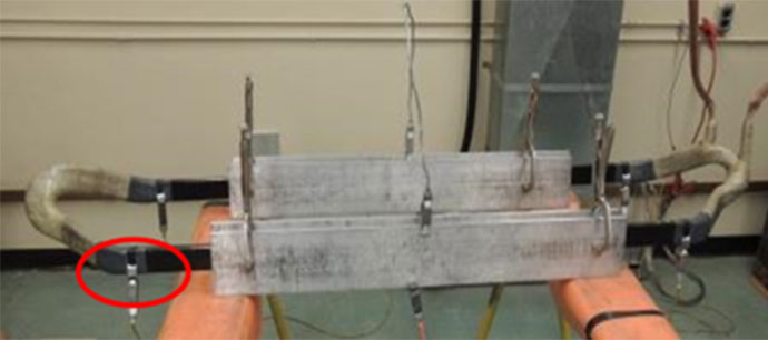
Figure 1: A 13.8 kV stator coil undergoing dissipation factor testing with guard electrodes. One of the guard electrodes is circled in this photo. (Photo courtesy of Kinectrics)
Example Test Results
The results obtained from the analysis of the data are presented in Figures 2 and 3. There are a few points to note regarding these Figures.
- Process A and B refer to the two different manufacturing methods commonly employed, however, the actual processes are not identified because it is not the objective of this work to imply that one manufacturing method is superior to the other.
- According to the IEC standard, a dissipation factor measurement is accomplished by recording data at 0.2UN and 0.6UN, where UN is the nominal phase-to-phase voltage of the stator winding. For a 13.8 kV system, these voltages correspond to 2.8 and 8.3 kV respectively. However, in this case, the North American convention was followed and the results were derived at 2 and 8 kV.
- The limits referred to in Figures 2 and 3 are those stipulated in IEC 60034-27-3 and are reproduced in Table I below.
TABLE I. Dissipation Factor Limits
(source: IEC 60034-27-3, Table 1)
| Initial value of dissipation factor at 0.2UN | 20 x 10-3 (2%) |
| ΔDissipation factor per 0.2UN up to UN | 5 x 10⁻³ (0.5%) |
| Dissipation factor tip-up between 0.6UN and 0.2UN | 5 x 10⁻³ (0.5%) |
Examination of Figures 2 and 3 reveals a number of features. These are,
- All of the coils and bars tested were well within the prescribed absolute dissipation factor limit of 20 x 10-3 (2%) defined in IEC 60034-27-3. The maximum value recorded was 13.54 x 10⁻³ (1.354%).
- With respect to the dissipation factor tip-up limits set out in IEC 60034-27-3, a number of stator bars or coils would not have met the requirements of the standard. Approximately 20% of the Process A bars or coils and 15% of those stator winding elements manufactured using Process B exhibited dissipation factor tip-up values above 5 x 10⁻³ (0.5%).
This limited data implies that the absolute dissipation factor limit at 0.2UN recommended by IEC 60034-27-3 may be too conservative and that some consideration of this criterion may be advisable in any future revision of the document. In contrast, the findings from an examination of the dissipation factor tip-up values showed that a significant number of bars or coils failed to meet the limit required by the standard. 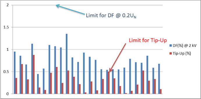
Figure 2. Dissipation factor % and tip-up %results for 26 groups of coils and bars manufactured using Process A.
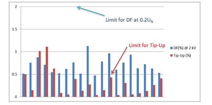
Figure 3. Dissipation factor % and tip-up % results for 20 groups of coils and bars manufactured using Process B.