
IEEE TRANSACTIONS ON ENERGY CONVERSION, VOL. 27, NO. 4, DECEMBER 2012
Abstract – Online magnetic flux monitoring via permanently in-stalled air-gap flux probes is a well-established technology to determine the presence of shorted turns in a turbine generator rotor winding. Flux measurements are normally performed using flux probes installed in the machine air gap (on a stator wedge) and connected to portable or permanently installed instruments. In this “flux probe” test, to achieve a reliable diagnostic, the signal from the flux probe has to be measured under different load conditions ranging from no load to full load. This requirement presents a serious obstacle when applying this method on base load units. Recently, a new design of magnetic flux probe installed on the stator tooth was implemented. In addition, new algorithms used to analyze measurements using different types of flux probes were developed to minimize the need for tests at different load conditions. A finite element model (FEM) has been created to verify these new algorithms in different loading conditions. Based on this model, and real-world measurements, it has been demonstrated that accurate detection of shorted turns can be obtained without the need to vary the load on the machine if suitable sensors and algorithms are applied. This paper describes the new method and its advantages, comparing results obtained from online measurements on working generators and the FEM created to simulate different rotor conditions.
Index Terms—Finite element, flux density, flux probe, rotor shorted turns, synchronous generator.
I. INTRODUCTION
A turbine generator rotor typically consists of a solid forging made from magnetic alloy steel and copper windings, assembled in slots machined in the forging. The winding is secured in slots by steel, bronze, or aluminium wedges (see Fig. 1). At each end of the rotor, end sections of the rotor winding are supported by retaining rings. Modern rotor winding electrical insulation is made mostly from epoxy-polyester glass composites and/or Nomex laminate strips and channels. The strips are used to provide interturn insulation and moulded channels are used to provide slot (ground) insulation.
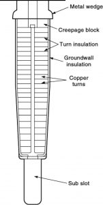 Fig. 1. Typical cross section of a turbine generator rotor slot.
The rotor body is machined to accommodate the rotor winding, and on two-pole rotors, there are usually between five and nine slots per pole. Conductors on each pole are distributed on both sides of pole face, as leading and lagging coils (see Fig. 2). By convention, lower numbered coils are closer to the pole face and higher numbered coils are closer to the rotor quadrature axis. Some rotors will have additional slots for an amortisseur (damper) winding for transient stability, visible in Fig. 2, directly under the pole face (in green, marked with A) and these slots are usually not assigned a number. The rotor shown in Fig. 2 has 14 slots for the rotor winding on each pole (seven leading and seven lagging), and four slots for the amortisseur winding.
The rotor insulation system is designed to withstand electrical, mechanical, thermal, and environmental stresses. Shorted turns are the result of failed insulation between rotor turns, which is a common occurrence in large turbine genera-tors. Major causes of shorted turns in rotor windings are as follows [1], [2]:
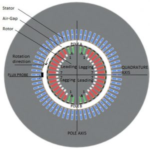
Fig. 2. Turbo generator cross section, lower numbered rotor coils are closer to pole face/axis.
- contamination with conductive debris;
- relative movement of the turns during turning gear operation leading to copper dusting;
- axial thermal expansion during load cycling that can abrade the turn and slot insulations, or cause migration of the turn insulation strips in the endwinding area, leading to shorts;
- long-term thermal aging of the insulation.
Puncture of the turn insulation does not result in the failure of the generator, and in fact it is sometimes possible for rotors to continue to operate with a few shorted turns [2].
Different factors will affect how serious the problem caused by rotor winding shorted turns will be. In many cases, the rotor will still run without significant consequences, as long as the excitation system can compensate for lower number of active turns in the rotor winding. However, the most noticeable effect can be increased rotor vibration. Since the resistance of coils with shorted turns is lower, they are likely to operate at lower temperatures compared to coils without shorted turns. This temperature difference will cause uneven heating of the rotor forging and can cause the rotor to bow. The bowing will increase with increasing load due to higher temperatures resulting from higher excitation current and may cause rotor vibrations. Therefore, this situation is frequently described as thermally sensitive vibration. Two-pole rotors are much more sensitive to thermal vibrations than four-pole rotors.
The condition of the rotor winding turn insulation is difficult to assess during a shutdown due to limited access and the frequently intermittent nature of faults at operational speed, and at standstill. As a result, online testing is a more effective way to detect shorted turns. Magnetic flux monitoring using temporary or permanently installed flux probes was developed in the early 1970s to find rotor winding shorted turns when the rotor is spinning [3]. Flux probes are flexible or nonflexible polymer encased coils protruding into the air gap between the rotor and stator. A traditional flux probe is fixed to a stator winding wedge. A voltage is induced in the stationary flux probe as each rotor slot (dc current carrying conductor) passes by during operation, resulting in a peak of measured voltage as shown in Fig. 3. The measured voltage is integrated and zero crossing of integrated curve is described as flux density zero crossing (FDZC). To date, all shorted-turn online test methods are based on the measurement of the relatively weak stray flux (rotor slot “leakage” flux) using stator wedge-mounted probes [4]–[6]. The stray flux is proportional to the total ampere-turns in each rotor slot. If shorts develop between turns in a slot, then the ampere turns in that slot drop, and stray flux across it is reduced. The magnitudes of the voltages from these stray fluxes can be measured using portable or permanently installed instruments. Since the leakage flux density is very small compared to the main magnetic flux density, the conventional test requires the user to measure the voltage from the leakage flux at or near the FDZC, so that a change in the leakage flux caused by a shorted turn can be more readily detected. As is discussed later, with the conventional flux probe test method, the only way to have sensitivity to shorted turns in all coils (slots) is to change the position of the FDZC so that it passes through each slot. This can only be accomplished by changing the generator load from no load to greater than full load.
This paper describes a new flux test approach that does not always require the maneuvering of the generator load from zero to greater than full load. The results obtained from online measurements on working generators are verified by a finite element model (FEM) created to simulate different rotor conditions. The FEM is first described. Then, a description of how to analyze the results from the conventional flux probe test is described, followed by a summary of a new approach to the flux probe test.
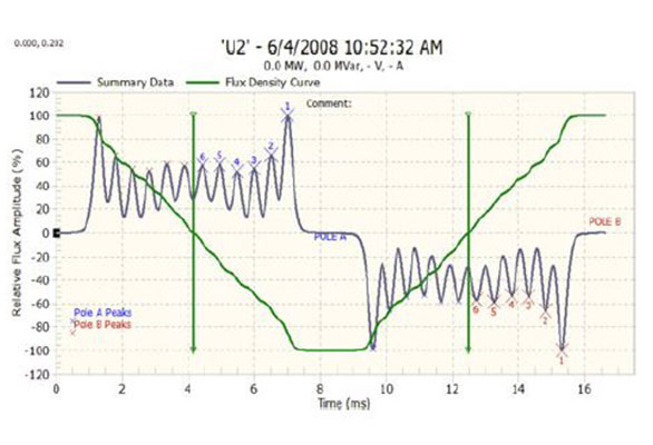

Fig. 3. Voltage induced in a flux probe, shown by the gray line. The leading coils of each pole are numbered. The green (quasi-sinusoidal) line is the integrated flux density. The vertical dark green line is the location of FDZC. No load condition shown.
II. MAGNETIC FLUX FINITE ELEMENT CALCULATION
Two-dimensional magnetic flux models were created using an FEM, replicating actual generators where flux probes were installed and for which magnetic flux measurement data were available. Since flux probes are generally mounted 0.2–0.5 m from the end of the stator core where the effects of the axial flux component are not present, 3-D modeling was not required. Powerful analytical tools like an FEM generate realistic results with properly selected starting and boundary conditions. These techniques make it possible to calculate the distribution of the magnetic field and induced voltages in stator and rotor windings, as well as in flux probes installed in the air gap. With suitable adjustments to the model, the effect of different operational modes, including presence of various faults within stator or rotor windings can be calculated. Accuracy of such models depends on the availability of original generator design data (dimensions and materials used) and density of the FEM mesh. A model is needed for each generator studied. The first step in the modeling process is to create a model of a generator as close as possible to the real machine, using original design data and dimensions. The next step is to create FEM mesh. In the two models described in this paper, the highest density of FEM mesh was used in the air gap and parts of the rotor and stator facing the air gap (see Fig. 4). Initially, a model with very high mesh density was created, and later optimized to reduce computation time. The maximum mesh element size in rotor and stator body was 30 mm, and in the air gap 1–2 mm. Comparison of FEM results with real measurement indicated that keeping the mesh element size down to 1–2 mm only in proximity of the flux probe, and increasing it to 10 mm for the rest of the air gap significantly reduced computing time without any loss in quality of the data. The software used to create the models is Infolytica-MagNet, version 7.1.1. For each computation, the run time was about 5–7 h and more than 300 FEM runs were made in this study. Starting from static model, load was increased in small steps, and calculations made for each coil, in various conditions. Artificial shorts were created on one of the poles, and detection sensitivity to each short verified at all loads.
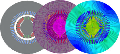
Fig. 4. Steps taken in modeling a two-pole 266-MVA generator.
III. CONVENTIONAL FLUX PROBE TEST ANALYSIS
In a conventional flux probe test, shorted turns can be identified by comparing the difference in the induced voltages from pole to pole [1]–[5]. To determine existence of a shorted turn, a comparison of “leading” slot coils, one pole to another pole, is performed (see Fig. 11). Where the FDZC occurs, the signal is most sensitive to the reduced leakage flux from the slot caused by a turn short. By inverting the leakage flux plot and subtracting it from the plot from the other pole, any difference in the plots at the FDZC position may indicate a short in the coil at the FDZC with the lower leakage flux. This, of course, assumes that the coils around pole A do not have exactly the same shorts (position and resistance) as on pole B.
The main challenge with the existing technology is the need to maneuver the generating unit load to achieve the maximum sensitivity to shorted turns in every slot of a rotor and to look for changes in the leakage flux when the FDZC is at each slot. This is increasingly difficult to achieve in power systems controlled by independent system operators, where a power plant operator has very limited freedom to change the load to perform testing.
For a specific two-pole generator rated 13.8 kV, 60 Hz, 115 kVA, the FEM and flux probe test shows that at no load, the FDZC is located near to coil 6 (see Figs. 5 and 6). Figs. 7 and 8 show the flux probe measurement and the associated FEM calculation at a higher load for the same generator. It is clear from Figs. 6 and 8 that the higher load “rotates” the magnetic field within rotor and FDZC to a different position, in this case to coil 4.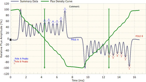
Fig. 5. Low load condition test where the voltage induced in the flux probe is shown by gray line, the integrated flux is shown by green line, and the FDZC is indicated by vertical green line. The FDZC is located on leading slot coil 6.
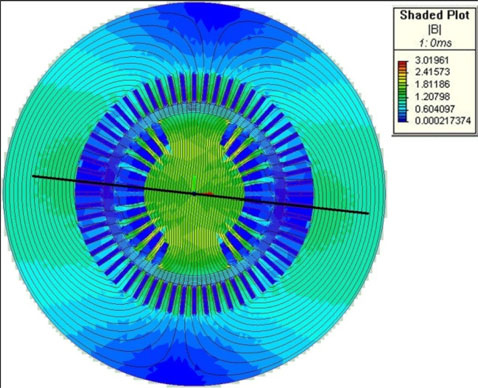
Fig. 6. Flux density calculated by an FEM for the example in Fig. 5 for the no load condition. The flux density zero location is indicated by black line, located on coil 6. Note that the blue color indicates location of near-zero magnetic flux.
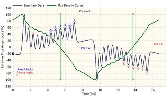
Fig. 7. Higher load condition test, voltage induced in Flux probe shown by gray line, integrated flux shown by green line, and FDZC indicated by vertical green line, located on peak caused by leading coil number 4 of pole A and coil 4 in pole B.
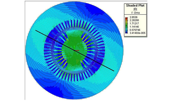
Fig. 8. Flux density at higher load, flux density zero located on leading coil number 4.
The requirement to change load to achieve sensitivity to shorted turns in all coils can be a serious obstacle to detect a shorted turn in coils furthest from the pole face in base load units running consistently at, or close to, full load. At full load, the FDZC is usually closest to coil 3 (closer to the pole axis). To detect shorts in coils 1 and 2, using conventional technology, the generator needs to produce maximum active load and maximum negative reactive load. Such a load condition may not be possible to achieve in normal operation. Furthermore, shorted turns in coils 1 and 2, which are closer to the pole face, are much bigger contributors to rotor-bearing vibration then shorted turns in coils with higher numbers. Thus, shorts in coils 1 and 2 have more impact on generator operation, yet are harder to detect using the flux probe test [8].
IV. ALTERNATIVE FLUX ANALYSIS METHOD
New hardware and algorithms were developed in an attempt to make the flux test sensitive to shorted turns in all coils, even if the generator load could not be changed to move the FDZC to be aligned with all slots. One aspect was to improve the temporal and magnitude resolution of the hardware compared to the conventional test. Another aspect of the approach is to concentrate on the main magnetic flux rather than the leakage flux. Third, three different proprietary numerical methods were developed to improve the sensitivity to small differences between poles A and B main flux plots. Finally, the results from the three algorithms were compared to develop an index of the confidence in the conclusion of the presence (or not) of shorted turns in each coil. Some details of the method are presented in [9].
The new approach can be used with conventional wedge-mounted coils that protrude into the air gap. However, an alter-native probe was also developed that can be glued to the stator core tooth, rather than the stator wedge (see Fig. 9). This probe, known as a total flux probe (TFProbe), directly measures the main magnetic flux that passes through the core tooth [7]. An advantage of a tooth-mounted probe is that with suitable tooling, it can often be retrofitted even if the rotor is not removed from the generator. Fig. 10 shows a photo of a tooth-mounted probe being installed with the rotor in place.
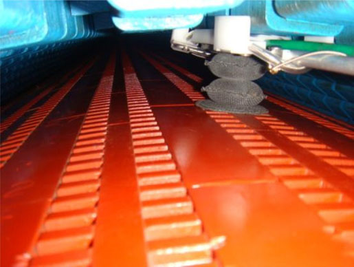
Fig. 10. TF probe installation with rotor in situ.
As discussed earlier, detection of shorted turns in two-pole and four-pole rotors is usually performed based on a comparison of voltage induced in the flux probe, by coils of one pole to coils of another pole (see Fig. 11). It is clear in Fig. 11 that the FDZC (vertical green line) is in the least favorable position for detection of shorted turns in coil 2, when the test was conducted in no load or low load condition. Despite this, it is easy to see the difference between poles A and B results in coil 2 and conclude that the number of active turns in coil 2 of pole A is lower than in coil 2 of pole B.
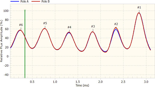
Fig. 11. Pole-to-pole comparison, shorted turns detected in pole A, coil 2 with FDZC in an unfavorable position since the generator is not fully loaded.
The reduction in flux probe voltage measured from a rotor coil with shorted turns is the consequence of the number of shorted turns, position of FDZC, and the turn-to-turn resistance of the short. Theoretically, in the position of maximum sensitivity (FDZC aligned with the coil), this probe voltage drop will depend only on the number of shorted turns and the resistance of the short. The probe voltage induced by a coil with 9, instead of 10, active turns should be 90% of the voltage induced by a coil with no shorted turns, assuming the resistance of the short is 0 Ω. In real measurements, however, the effects of temperature and the resistance of the short will influence the reduction of voltage induced by a rotor coil with shorted turns, and it will rarely if ever, exactly correspond to the number of shorted turns. Therefore, detection of shorted turns cannot be based only on integral-induced voltage reduction, where one shorted turn is responsible for a fixed percentage voltage reduction [10].
V. CASE STUDY 1—TWO-POLE 266-MVA GENERATOR
The purpose of this study was to verify capabilities of an FEM on a generator without shorted turns in the rotor winding, and to confirm the accuracy of the FEM by comparing results to the real flux probe test measurement performed on a two-pole, 13.8-kV, 50-Hz, 266-MVA, generator with an air gap of 80 mm. The FEM was used to calculate flux probe signals corresponding to different loads for a generator without shorted rotor turns and for the same generator with different position of coils with shorted turns.
A stator tooth-mounted TF probe was installed in this genera-tor after a rotor rewind and tests were made at normal operating load. The coil numbers, integrated value of flux and locations of FDZCs are automatically determined by a specialized portable instrument during the data acquisition. No shorted turns were detected.
Fig. 12 shows a comparison of FEM calculations and measurements on the same graph for this generator without shorted turns in the rotor windings. Since all generator design data were known, an excellent agreement between FEM calculation results and real measurement has been achieved.
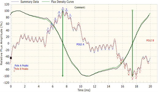
Fig. 12. Comparison of measured (gray–green) and FEM calculated data (dashed lines, red–black).
The next step in the process was to model shorted turns in different coils and determine the sensitivity to shorted turns detection at different loads and thus different positions of FDZC’s. There are seven coils on each pole of this rotor with 12 turns in coils 2–7 and eight turns in coil 1. Using an FEM, a shorted turn was modeled in each of the seven coils and the sensitivity to these shorted turns in different locations was evaluated for different generator load and test conditions, resulting in more than 200 different models.
As an example, one shorted turn was simulated in coil 5 and the sensitivity was evaluated at different loads, corresponding to positions of FDZC from coils 7 to 1. The results are shown in Fig. 13. In a coil with 12 turns, the reduction of active turns to 11, in perfect conditions (i.e., the turn-to-turn resistance is 0 Ω) will result in a voltage drop of 8.33%, which was the result of FEM calculations for perfect position of FDZC. Although sensitivity to shorted turns in coil 5 is somewhat lower with less favorable positions of FDZC, detection of shorted turns is possible at any load. As demonstrated in Fig. 13, there is no requirement to change the load for initial condition assessment of any rotor coil. Similar results have been obtained for many machine designs, both in practical measurements and using the analytical FEM model.
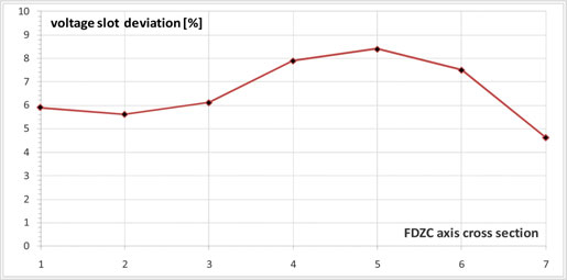
Fig. 13. Poles A to B difference at different loads (FDZC Points), shorted turn in coil 5.
VI. CASE STUDY 2—TWO-POLE 115-MVA GENERATOR
A series of tests that were conducted using the new flux probe measurement and analysis approach indicated a consistent sensitivity to shorted turns in the highest numbered coil on a two-pole 13.8-kV, 115-MVA, 60-Hz turbine generator under different loading conditions. Fig. 14 indicates the poles A to B leading slots comparison at the maximum load available, 80-MW, 12-Mvar lagging. A shorted turn in coil 6 is clearly identified in Fig. 14, although the FDZC is far away from this coil, at coil number 3.
Fig. 15 shows a comparison of poles A to B leading slots, at the minimum load available during the tests performed on this generator.
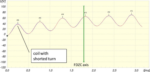
Fig. 14. Pole-to-pole comparison, measured from a flux probe when the generator was operating at the highest available load.

Fig. 15. Pole-to-pole comparison, based on measured data collected at min-imum load available. The FDZC is as the optimum position to detect the turn short in coil 6.
In both plots, the vertical green line is an indication of the FDZC position that is close to coil 3 for an 80-MW load (see Fig. 14) and close to coil 6 at no load condition (see Fig. 15). Fig. 16 shows a summary of multiple actual flux probe test measurements performed on this generator at different loads, where it can be seen that voltage induced by coil 6 (red square) on pole B is consistently lower then on pole A, at all loads (i.e., positions of FDZC). Coils without shorted turns (1–5) are expected to have equal peak amplitudes, compared to the opposite pole, and normalized pole to pole difference for coils without shorted turns was always lower than 1% (the true noise floor of the measurement system).
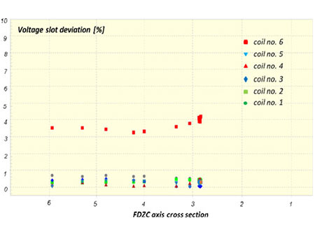
Fig. 16. Measured flux probe voltage slot deviations for all slots and different generator loads with shorted turn present in the slot number 6. The horizontal axis is FDZC position in a reference to coil number, and the Y -axis is the normalized flux difference from poles A to B in percent for each of six coils.
Although not all generator design data and materials were known, a magnetic flux FEM was created for this generator and comparison of an FEM and actual measurement flux test data for the same loading condition is shown in Fig. 17.
Using the FEM, a single-shorted turn was created in coil number 6, and a simulation of a load change in similar steps as it was done on the real generator, is shown in Fig. 18.

Fig. 17. Comparison of real (gray–green) and FEM calculated data (dashed line, red–black).
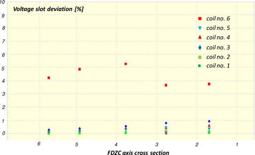
Fig. 18. Calculated induced voltage slot deviations for all slots and different generator loads with a single shorted turn present in the slot number 6. The horizontal axis is the FDZC position, the vertical axis is the normalized flux difference from poles A to B in percent for each of six coils—data from FEM study.
The FEM results agreed well with the real measurement results for coils with shorted turns and coils without shorted turns. Coil 6, with one shorted turn in all loads, had a pole-to-pole difference greater than 3% and coils 1–5, without shorted turns had a difference smaller than 1% (see Fig. 16 for real measurement and Fig. 18 for FEM calculated data).
Again, this demonstrates the ability to detect shorts regardless of the load on the machine.
VII. CASE STUDY 3—TWO-POLE 180-MVA GENERATOR WITH MAGNETIC WEDGE
In addition to studies on effects of shorted turns, we used the FEM to evaluate the impact of magnetic wedges on the flux probe test. Magnetic wedges are sometimes used on older rotors, especially at each end of the rotor slots. In situations where only one of the rotor slot wedges has different magnetic properties, flux measurement analysis could lead to a wrong conclusion if flux probe test analysis is limited to the evaluation of one coil only. A two-pole, 13.8-kV, 180-MVA generator had a single magnetic wedge installed in a single slot (by accident). Actual flux probe measurement (see Fig. 22) showed that the flux probe voltage was modified from expected. This case study simulated the real machine measurements using an FEM.
Fig. 19 shows the simulated impact of a magnetic wedge mounted in one slot only (in slot 1, the first two slots are used for amortisseur winding). The voltage induced in a simulated flux probe was also calculated as shown in Fig. 20, this time for the wedge installed in slot 3. Different magnetic permeability values were used in the model to evaluate their impact on detection of rotor shorted turns. Results shown in this case study are based on permeability values that created deformation similar to the indication of a single shorted turn. From Figs. 19 and 20, it can be seen that existence of a magnetic wedge in one slot will affect the magnetic field in adjacent slots as well, and consequently, the voltage induced in a flux probe will be modified in the adjacent slots. This is not the case if the reason for reduction of induced voltage in the flux probe is shorted turn, as shown in Fig. 21.
However, based on the FEM study and real measurement data (see Fig. 22), it is possible to differentiate between the effects caused by a lower number of active turns in a slot (a real short) and the effects caused by different magnetic property of a wedge with no short present.
Results shown in Fig. 22 are from a generator with known problems and used here as an illustration of real effects of magnetic wedge, mistakenly installed in this slot. No FEM study was performed for this generator.
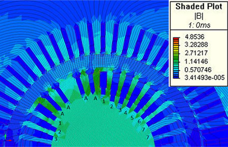
Fig. 19. Effect of magnetic wedge in slot 1 on field distribution.

Fig. 20. Effect on the voltage from a simulated flux probe due to a simulated magnetic wedge in slot number 3 of pole A.
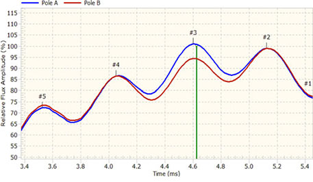
Fig. 21. Effect of shorted turn in slot number 3 of pole B with no magnetic wedges, FEM study data.
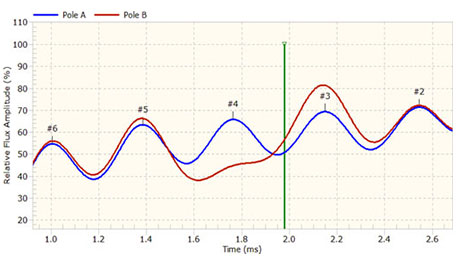
Fig. 22. Effect of magnetic wedge in slot number 4, actual measurement from a flux probe.
VIII. CONCLUSION
An FEM has been developed and verified to accurately simulate real magnetic flux conditions in synchronous machines. Based on this model, it has been demonstrated that with suitable instrumentation and algorithms, accurate detection of turbine generator rotor winding shorted turns can be obtained in most of the cases without the need to vary the load on the machine. This advancement greatly improves the viability of online flux monitoring for shorted turn detection in practical generation applications where it is sometimes difficult to change the load in a controlled fashion. Sensitivity to shorted turn is different at different loads, as indicated in Case study 1, but use of new algorithms and high sampling accuracy, provided sufficient sensitivity regardless of the load on the machine. Furthermore, detection of shorted turns in coils 1 and 2 (close to the rotor poles) is possible without having to overload the generator.
Comparison of over 300 FEM simulations and flux probe measurements obtained from real generators confirmed that an accurate FEM can provide results virtually identical to real data, as long as design parameters of the generator are known. Case study 3 also provides details on how magnetic wedge materials will distort the flux in a manner that is different from true turn shorts. This information further improves the certainty of online monitoring for turn short detection in rotors.
REFERENCES
[1] G. Klempner and I. Kerszenbaum, Handbook of Large Turbo-Generator Operation and Maintenance, 2nd ed. Piscataway, NJ: Wiley/IEEE Press, 2008.
[2] G. C. Stone, E. A. Boulter, I. Culbert, and H. Dhirani, Electrical Insulation for Rotating Machines. Piscataway, NJ: Wiley/IEEE Press, 2004.
[3] D. R. Albright, “Inter turn short-circuit detector for turbine-generator rotor windings,” IEEE Trans. Power App. Syst., vol. PAS-90, no. 2, pp. 478–483, Mar./Apr. 1971.
[4] D. R. Albright, D. J. Albright, and J. D. Albright, “Generator fields wind-ing shorted turn detection technology,” presented at the Iris Rotating Mach. Conf., Scottsdale, AZ, May 1999.
[5] M. P. Jenkins and D. J. Wallis, “Rotor shorted turns: Description and utility evaluation of a continuous on-line monitor,” presented at the EPRI Predictive Maintenance Refurbishment Conf., San Francisco, California, Dec. 1993.
[6] A. Whittle, “Continuous rotor flux monitoring,” presented at the EPRI Gener. Workshop, Phoenix, Arizona, Aug. 2007.
[7] Flexible Printed Circuit Magnetic Flux Probe, U.S. Patent 6 466 009, Oct. 15, 2002
[8] G. Klempner, “Rotor shorted turns-detection and diagnostics,” presented at the EPRI Gener. Predictive Maintenance Refurbishment Conf., Orlando, Florida, Dec. 2003.
[9] M. Sasic, B. A. Lloyd, and S. R. Campbell, “Flux monitoring improve-ment,,” IEEE Ind. Appl. Mag., vol. 17, no. 5, pp. 66–69, Sep./Oct. 2011.
[10] M. Sasic, B. A. Lloyd, and A. Elez, “Finite elements modelling of rotor shorted turns,” presented at the EPRI TGUG Workshop, Barcelona, Spain, 2011.
Mladen Sasic (M’93–SM’08) received the B.S. de-gree in electrical engineering from Sarajevo Univer-sity, Sarajevo, Yugoslavia, in 1987.
He is currently a Manager of Rotating Machines Technical Services at Iris Power, Mississauga, ON, Canada. He has more than 25 years of experience in design and testing of electrical power equipment.
Mr. Sasic is a Registered Professional Engineer in Ontario, Canada.
Blake Lloyd (M’85–SM’99) received his BASc. degree in electrical engineering from University of Waterloo, in 1983. He is currently the Director of Product Development for Iris Power, Mississauga, ON, Canada. He is also an Electrical Engineer with extensive experience in instrumentation and product development. Previously, he worked in software development and then in the Electrical Research Department, Ontario Hydro, where he was responsible for conducting research into advanced measurement, testing, and diagnostic monitoring techniques for rotating machines and insulation systems. Since co-founding Iris Power in 1990, he has been one of the principle architects of Iris’s line of partial discharge-related instrumentation and analysis software. He has two U.S. patents, and has published 16 refereed papers in IEEE and Conference Internationale des Grands Reseaux Electriques, as well as more than 40 conference papers.
Ante Elez received the Master’s and Ph.D. degrees in mechanical engineering from the Department of Electrical Machines and Automation, Faculty of Electrical Engineering and Computing, University of Zagreb, Zagreb, Croatia, in 2008 and 2010, respectively.
He is currently a Project Manager at KONCAR-Electrical Engineering Institute, Zagreb, Croatia. He has eight years experience working in Rotating Machines Department. His scientific research and development activities are aimed at measuring and analyses of electric machine parameters. He is the author of ten papers published in proceedings of scientific conferences.