
Partial Discharge Testing of Stator Bars and Coils as a Quality Assurance Test
Partial discharge (PD) testing is one of the most widely used methods to assess the quality of electrical insulation in new high voltage equip-ment such as power cables, transformers and switchgear. IEEE and IEC standards specify how to perform the PD test, identify what magnitude of PD (in picoCoulombs) is permitted, and what the test voltage is for each of these types of equipment. Stator windings in motors and gen-erators are different. To date, IEEE 1434 and IEC 60034-27 identify how to perform the PD test on coils/bars as well as windings, but there is no standard that recommends the PD magnitude that is acceptable nor the test voltage, either for bars/coils or for complete windings. It seems reasonable that a standardized PD test for new stators is not available since each brand of PD detector will produce significantly different lev-els of PD, making it hard to obtain consistent results. However, recently there has been some investigation on developing a PD quality assurance (QA) test for stator bars and coils.
In power cables, transformers and switch-gear, PD can occur if small voids are created within the insulation during manufacture, or air gaps occur between conductors at different volt-age levels. The primarily-organic insulation in these types of equipment deteriorates when exposed to prolonged PD, growing “electrical trees” or developing surface tracking. Eventually, the organic insulation (polyethylene, oil, pa-per or epoxy) will puncture, causing failure in as short a time as a few months. The PD quality assurance test ensures that no such voids or gaps are created during manufacturing, that would result in premature failure of the equip-ment.
Voids within the groundwall insulation of new bars and coils rated 3 kV and above can occur for a variety of reasons, such as by wrin-kling of the mica paper tapes, poor control of the liquid epoxy chemistry and viscosity (VPI pro-cess), insufficient time for epoxy impregnation (VPI process), inadequate pressure for resin rich tapes, etc. If these voids are within the groundwall (see Figure) and the coil is connected to the high voltage terminal of the motor or generator, then PD may occur within the voids. Because almost all machines rated 3 kV and above are made with mica paper tapes, which are very resistant to PD attack, it may take years or even decades for a failure to occur in service. Thus PD is not as catastrophic for a motor or generator as it is for other types of high voltage equipment. But there is still interest in an objective, non-destructive test that can assess if severe voids are present.
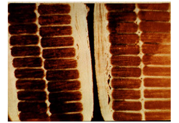
One such test for voids is the dissipation factor tip-up test (IEEE 286 and IEC 60034-27-3). The tip-up is an indirect method of measuring the PD activity. However, the tip-up test cannot distinguish between one large void and many small voids in a coil or bar since it measures the average condition of the coil or bar. The other way to detect voids is directly with a PD Quality Assurance test. The advantage of the PD QA test is that a modern digital PD test can measure the severity of the largest voids (the peak PD magni-tude), and give an indication of the number of voids (from the PD pulse repetition rate). Another advantage of the PD test is that the phase-resolved PD pattern can be used to determine where the voids are located within the ground-wall (i.e. near the coil/bar surface, or closer to the copper conductors, as is the case in the figure).
One of the technical problems with a factory PD test on coils and bars is that different brands of PD instruments seem to detect different levels of PD on the same coils/bars. Recently GE and EDF have published IEEE papers where PD was measured on the same coil using 3 different brands of PD test instrument [1,2]. The tests were done with instruments using the IEC 60270 frequency range (< 1MHz). The PD levels differed by as much as three to one. That is, 100 pC might be measured with detector 1, but detector 2 might yield 300 pC, on the same coil. This variation means that a coil might pass using one instrument, but fail using another. The reason for the variation between brands is unknown, but it could be caused by:
- Each brand of detector tends to use slightly different PD detection frequencies, yet still be within the IEC 60270 range.
- The meaning of peak PD magnitude that is used in ASTM D1868 and IEC 60270 is based on an analog concept that does translate easily for modern digital PD detectors. It seems different PD equipment manufacturers calculate the peak PD magnitude differently in their modern digital PD detectors.
Until these two issues are resolved, it will be difficult to obtain a consistent PD magnitude between brands. So, although IEEE Electrical Machines Committee/Materials subcommittee is now attempting to draft a PD test standard for coils and bars, progress will probably have to wait for consensus on specific frequencies and a digital method of calculating peak PD magnitude.
References
- A. Petit, “Temperature effect on insulation resistance of generator stator bar affected by water ingress”, IEEE Electrical Insulation Conference, June 2015.
- S. Ul Haq, et al, “Comparative Study of IEC 60270 Compliant Instruments for PD Pattern Acquisition, IEEE Petrochemical Industry Conference, September 2016.§