
Abstract- Diagnostic tests such as insulation resistance, polarization index, dissipation factor, capacitance and partial discharge can be useful to diagnose the condition of the stator winding insulation, and identify many problems that could lead to insulation failure. Many years of experience, however, has shown these quantities by themselves cannot predict the remaining life of a winding. However, asset managers would prefer an estimate of the remaining stator winding insulation life. Knowing the remaining life allows asset managers to obtain the maximum use from the existing winding, while avoiding in-service failures and permitting the planning of the optimal time to rewind. Over the years, various machine repair organizations in Japan, Europe and India have claimed the ability to determine the remaining life. This paper examines the literature and practical experience using these remaining life estimation tools. It is concluded that there is no evidence that the available tools provide an accurate estimate of the remaining life. A protocol is suggested for evaluating the validity of any new method to estimate remaining life.
I. MOTIVATION FOR WINDING INSULATION LIFE PREDICTION
Plant managers and asset managers are not interested in diagnostic test results. Instead, they want to know when a motor or generator stator winding will fail. Since about 50% of machine failures are caused by winding insulation failure [1,2], it is obvious that they want to know the remaining (or residual) life of the windings. The reasons for wanting to get a good estimate of the remaining life are:
• To maximize the capital investment they have in the existing winding – i.e. to make it last as long as possible.
• To avoid in-service failure, with the consequent unexpected loss of production and the possibility of far more damage and repair costs than if the winding was repaired or replaced prior to an in-service failure.
• To budget (plan) for repairs or rewinds with at least a year or so forewarning, so that the cost and time for the repair can be anticipated and minimized.
There are a number of off-line and on-line diagnostic tests for winding insulation that have been widely used for many decades [3,4]. These include insulation resistance, polarization index, capacitance, dissipation factor and partial discharge (on-line and off-line). As discussed in relevant standards (IEEE 43, 286, 1434 and IEC 60034-27-1), it is well known that no individual test is a good predictor of remaining life. Instead the change in the test results over time, or the magnitude of the test result, can indicate that an insulation problem is developing.
The difficulty in predicting remaining life has several causes:
- There are in fact >20 different winding insulation failure processes [1]. It is not realistic to assume that one single test is equally sensitive to all these different failure mechanisms, any more than a single blood test can find all diseases.
- Some failure processes are slow (e.g. endwinding discharge which can take decades to reduce the insulation strength) whereas others are relatively fast (e.g. vibration sparking or slot discharge). Yet all these mechanism can produce the same high PD or high tip-up values.
- Although insulation does age, and presumably dielectric tests will reflect this aging, the actual moment of failure depends not only on the reduced mechanical and electrical strength of the winding, but also on the stresses applied. Often the actual time of failure is associated with a voltage or current transient (from voltage surges or power system faults) that exceeds the strength of the winding in its deteriorated condition. If the winding had not seen the transient, the winding may have survived for many years more. Without knowledge of the transient environment, reasonable estimates of remaining life will be very imprecise.
- Some common failure processes, such as endwinding vibration that leads to insulation cracking or abrasion, will not change any known dielectric property, except breakdown strength.
Nevertheless, plant/asset managers continue to encourage objective methods that can predict the remaining life for the reasons stated above. Thus machine manufacturers and/or their service organizations have developed several methods that they claim can predict remaining life. This paper reviews the three main methods that have been proposed and which have been commercially available over the years. In particular, their theoretical foundation is discussed, and evidence as to their effectiveness is presented. All three methods are based on using several different dielectric measurements that are combined together to give an overall assessment of remaining life. Remarkably, all have been supported by a tremendous amount of dielectric theory. First, a rapid review is made of the various individual diagnostic tests. A few are relatively new.
II. DIELECTRIC DIAGNOSTIC TESTS
There are several diagnostic test methods that have been in common use for decades and that are well documented in standards as well as books and papers [1, 3-5]. These include:
- Insulation resistance and polarization index tests, described in IEEE 43. These are low voltage DC tests that seem to be particularly sensitive to absorbed moisture or surface contamination.
- The DC stepped stress or ramp test to measure leakage current vs. applied DC voltage which is also sensitive to surface contamination, moisture and possibly insulation delamination. See IEEE 95 or [6].
- Dissipation factor tip-up (and the closely allied capacitance tip-up) as described in IEEE 286. In these two tests, the increase in dissipation factor with applied AC voltage or increase/decrease in capacitance as the voltage increases is a good indicator of widespread insulation delamination, although on complete windings, the presence of the silicon carbide stress relief coating can cause spurious changes, reducing sensitivity.
- Off-line or on-line partial discharge (PD) tests to directly measure PD occurring within insulation delamination, or surface PD caused by looseness in the slot, etc. These tests are described in IEEE 1434 and IEC 60034-27.
More recently, several other dielectric tests have been discussed. Some have been widely applied to dielectric assessment in liquid filled transformers and/or power cables.
The polarization/depolarization current (PDC) measurement is an off-line DC test where a significant DC voltage (from a few thousand volts to rated voltage) is applied to the winding, usually for about 1000s, and then the winding is grounded. The charging and discharging current is then measured [7, 8]. The polarization and depolarization currents should be low. If they are high, or they diverge from each other, then insulation problems are developing. One author claims that the earlier in time the two currents diverge from one another, then the closer the winding is to failure [7]. The test is apparently sensitive to contamination (as is to be expected), as well as surface insulation damage caused by coil vibration in the slot.
A variation on the PDC test is the recovery voltage measurement (RVM) [8-10]. RVM is now widely used to assess the deterioration in oil paper insulated transformers, where it has been found useful to detect thermal aging and moisture content. In this test a voltage is applied for say 1000 s, then it is discharged to ground for a period of time, and then the winding is disconnected from ground. The voltage then climbs to a peak voltage and then declines after a period of time. The peak voltage and the time to the peak voltage have been found to be significant indicators of aging in transformer insulation. It seems there has not been enough work to see if these factors are significant for machine insulation [9,10].
Another dielectric test is done in the very low frequency range (rather than with DC voltage). It is called dielectric spectroscopy [9,10]. An instrument applies a very low frequency AC to the winding, in the range of 0.1 mHz to a few Hertz, and the dielectric loss is measured. In some sense this is the frequency domain equivalent of the PDC or DC ramp test. Dielectric spectroscopy has been found to be useful in identifying power cables with water treeing.
More field experience is needed to see if any of these new tests provide additional information or are easier, cheaper or more reliable in finding the problems than the traditional IR/PI, tip-up and/or PD tests. However, experience with the PDC test, at least, is encouraging.
III. METHODS PROPOSED TO ESTIMATE REMAINING LIFE
It seems to be widely recognized that no single dielectric test can be used to estimate remaining life. However, several researchers have investigated whether combinations of dielectric tests can be used to estimate the remaining life of stator winding insulation. The following reviews three of these “combined test assessments” that have been proposed and employed commercially.
A. Residual Breakdown Voltage
Different Japanese researchers proposed an indirect way to estimate remaining life in the 1980s by first calculating the “residual” breakdown voltage from classical diagnostic tests including IR/PI, capacitance and dissipation factor tip-up and PD magnitude [11-13]. The idea was that if one could estimate the AC breakdown voltage of a winding from non-destructive diagnostic tests, then one could determine how close this estimated voltage is to the normal operating voltage (with perhaps some margin for normal voltage transients), and thus indirectly determine the remaining life. The key finding in these studies was that a combination of insulation resistance, polarization index, capacitance tip-up, dissipation factor tip-up and/or off-line PD peak magnitude could predict the residual breakdown voltage, and several experimental studies supported this contention. Regression equations were developed which would predict the residual breakdown voltage on windings from the diagnostic tests. Most of the supporting investigations were based on laboratory accelerated aging tests and/or using coils that were removed from the stator prior to diagnostic and breakdown voltage tests.
In the mid 1980s EPRI sponsored an extensive independent investigation to evaluate the validity of the residual life estimation method [5]. Four stators, one from a motor, one from a hydrogenerator and 2 from turbogenerators, were subjected to a range of diagnostic tests suggested by the researchers [11-13], and then coils/bars or parallels were tested to destruction with either 60 Hz AC, DC or impulse (1.2 microsecond risetime). All the testing occurred with the windings still in the stator. None of the stators were near their end of life, as judged by expert visual examinations, but they had seen one to three decades of operation. The results were disappointing. Figure 1 shows the scatter plot of the diagnostic quantity “K”, which is claimed to predict the residual AC breakdown voltage, and the measured breakdown voltage on a number of bars tested within the stator. There appears to be no correlation between K and AC breakdown voltage. Other predictive equations based on diagnostic tests showed equally poor correlation [5]. We are unaware of more recent research that indicates that the residual breakdown voltage approach is viable. Thus, we can only conclude that this approach may work in the laboratory, but not on real stators.
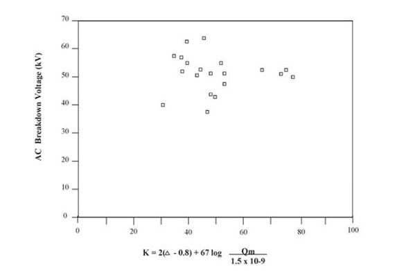
Figure 1: Correlation between the factor “K” based on conventional diagnostic tests and the measured breakdown voltage on several coils in a stator winding [5]. K is calculated from the peak PD magnitude, the dissipation factor tip-up the capacitance tip-up and the peak magnitude, Qm.
It seems that this method is still used today by some of the machine manufacturers.
B. Modified PD TestAlso in the 1980s, a test method called “TestACEC”, was proposed [14, 15]. ACEC was a Belgian rotating machine manufacturer. Instead of using the conventional diagnostic tests described above, Goffaux proposed a new technique that involved the measurement of “VBF”, as well as the more conventional peak PD magnitude (Qm). The method allowed the direct prediction of the remaining life of the stator winding insulation. The details of the method are proprietary, but it involved the measurement of PD at a lower than typical detection frequency. Goffaux suggested that the remaining life is better estimated by determining what happens to the charge after a partial discharge (rather than measuring the PD itself), and in particular if any mobile ions that result from the PD can accumulate to further degrade the insulation. The measurement used a modified Schering bridge, where the 50/60 Hz AC voltage was gradually increased to rated voltage. Although not published, it seems the Qm and VBF were measured in the few tens of kiloHertz range. A number of case studies were published that indicated that the new method correctly predicted remaining life (that is, failure occurred at the predicted time) [14, 15].
Again, EPRI sponsored an independent evaluation of this method [16]. In this case, since proprietary equipment was needed, the tests were done by the test developer. The testing was done on several 80 MVA hydrogenerators owned by Ontario Hydro. The condition of the generator stator winding insulation was well known (and ranged from excellent to poor) by the utility based on on-line and off-line conventional diagnostic tests, and most importantly, by expert visual examination. The researcher was unaware of the winding condition, prior to his assessment. The new method predicted that a few of the generators were at risk of imminent failure. This was in contrast to the utility assessment. In fact the machines predicted to fail operated for at least a decade longer, and were rewound only because the units were being uprated. Thus, it seems that independent (blind) evaluation did not validate the method. Apparently this method is no longer in commercial use.
C. Combined Dielectric Test and Life Method
Pinto has published several papers on the dielectric behavior of stator winding insulation over its life [17-19] and combined it with a model of how life is consumed to predict the remaining winding life in an approach called “LEAP”. Pinto was one of the first to suggest that DC polarization/depolarization current measurements may provide more information on the state of the stator insulation [17]. He also suggested that measuring the change in the dissipation factor and capacitance during the AC cycle could provide useful information that delamination was present [18], much as Simons and Dakin had done previously [20,21]. In his approach, Pinto also uses conventional IR/PI, off-line PD and tip-up tests. None of the papers indicate how one moves from the dielectric measurements to remaining life, and certainly none of the methods described above indicate that diagnostic tests alone can predict remaining life.
However, in a few case studies published in marketing literature, it seems that the new method assumes that each stator winding has an assumed design life (200,000 or 400,000 hours, roughly corresponding to 20 or 40 years), and the “life” is consumed linearly with hours of operation, with the addition of 20 hours for every machine turn-on. Presumably the AC and DC diagnostic tests amend this simple linear model for the consumption and yields a prediction of the remaining life (design life minus modified consumed life). The assumption that life is consumed linearly at a steady rate seems oversimplified. In addition, it is almost certain that machine manufacturers did not design the winding for a precise life such as 20 or 40 years, since apparently, even identical insulation samples will produce a 10 to 1 variation in life under thermal, electrical and mechanical accelerated aging tests [1]. If the method is predicated on an accurate design life, then the method seems flawed.
Unlike with the other prediction methods described above, to date there apparently is no independent verification by a third party on the validity of this new method. To validate the method, the test organization would need to disclose the method in its entirety to a third party to enable replication, or apply the method to several stator windings. The machines would then need to be operated to failure to determine the accuracy of the estimates.
IV. CONCLUSION
Asset managers desire accurate methods to predict the remaining life of equipment, and rotating machine stator windings in particular. Over the years at least three methods have been proposed which claimed to predict the remaining life, and thus enable asset managers to determine when repairs or replacement is required. In independent evaluation, two of these methods were not validated. Until independent evaluation is done on the most recent method to predict remaining life, there seems to be little scientific reason to expect this new method will be any more accurate.
The goal of remaining life estimation is a valid one. Based on the data above, it does not seem likely that diagnostic tests on their own can accomplish the task. Perhaps at best a probabilistic approach would be achievable.
REFERENCES
1) G.C. Stone, A. Boulter, I. Culbert, H. Dhirani, “Electrical Insulation for Rotating Machines”, Wiley – IEEE Press, 2004.
2) J.L.G. Araco et al, “Survey of Hydrogenerator Failures”, Electra, Oct 2009, p 31.
3) A.W.W. Cameron, “Diagnosis of AC Generator Insulation Condition by Nondestructive Tests”, IEEE Trans PAS, Part II, Jan 1952, p263.
4) W. McDermid, “How Useful are Diagnostic Test on Rotating Machine Insulation”, Proc IEEE Electrical Insulation Conference, Sept 1989, p 209.
5) G.C. Stone, H. Sedding, B. Lloyd, B. Gupta, “The Ability of Diagnostic test to Estimate the remaining Life of Stator Insulation”, IEEE Trans EC, Dec 1988, p833.
6) L. Lamarre, E. David, A. Nair, “Comparison of DC Ramp and DC Step Test Results on Hydrogenerator Stators”, Proc IEEE Electrical Insulation Conference, May 2009, p468.
7) S. Bhumiwat, “Field Experience in Insulation Diagnosis of Industrial HV Motors Using Dielectric Response Technique”, Proc IEEE Electrical E. Insulation Conference, May 2009, p454.
8) E. David, L. Lamarre, “Progress in DC Testing of Generator Stator Windings: Theoretical Considerations and Laboratory Tests”, IEEE Trans EC, 2010.
9) H. Sedding, “Application of Low Frequency Techniques for Stator Insulation Diagnostics”, Iris Rotating Machine Conference, June 2002.
10) S. Cherekupalli, “Application of Some Novel Nondestructive Diagnostic Tests for Condition Assessment of Stator Coils and Bars Following Voltage Endurance Tests”, Proc IEEE International Symposium on Electrical Insulation, June 2002, p 565.
11) K. Kadotani, et al, “An Approach to Insulation Diagnosis of Mica Resin Coils”, IEEE Trans PAS, Sept 1981, p 4136.
12) T. Tsukui, M. Takamura, Y. Kako, “Correlations Between Nondestructive and Destructive Tests on HV Coil Insulation”, IEEE Trans EI, April 1980, p118.
13) S. Itoh et al, “An Estimation of Breakdown Voltage of HV Motor Insulation by RC Value”, Electrical Engineering in Japan, 1984, p7.
14) R. Goffaux, J. Dacier, J.M. Frisson, “A Novel Electrical Methodology of Diagnosis for the HV Insulation of AC Generators”, Paper 11-12, CIGRE, August 1986.
15) M. Krecke, R. Goffaux, “Attempt at Estimating the Residual Life of the HV Insulation of AC Rotating Machines.” Paper 11-12, CIGRE, August 1988.
16) B. Gupta, “Discussion of Paper 11-12, CIGRE Session 11, Preferential Subject 2”, August 1988.
17) C. Pinto, “An Improved Method of Detecting Contamination of HV Stator Windings in the Field”, Proc. IEEE Electrical Insulation Conference, Oct 1991, p 55.
18) C. Pinto, “Variations in the Capacitance of Delaminated HV Stator Insulation Due to Electrostatically Generated Forces”, Proc IEEE Electrical Insulation Conference, Oct 1991, p65.
19) C. Pinto, “A Generalized Approach for Study of the Non-Linear Behavior of Stator Winding Insulation”, Proc IEEE International Conference on Conduction and Breakdown in Solid Dielectrics”, June 1998, p528.
20) T.W. Dakin, P.J. Milinaric, “A Capacitance Bridge Method for Measuring Integrated Corona-Charge Transfer and Power Loss per Cycle”, IEEE Trans PAS Part 3, April 1960, p 648.
21) J.S. Simons, “Diagnostic testing of high-voltage machine insulation. A review of ten years’ experience in the field”, IEE Proceedings B, Electric Power Applications, May 1980, p139.