
Abstract
The rotor windings of hydrogenerators are usually very reliable. However, the turn insulation in such machines will eventually degrade and puncture due to thermal aging, load cycling and/or contamination. Although turn shorts do not directly lead to machine failure, they can lead to high bearing vibration and may limit real and reactive power output. While off-line tests such as the “pole drop test” are available to detect rotor winding shorted turns, they are often unreliable since the rotor is not spinning for the test and the shorts may disappear (or vice versa). Forty years ago, an on-line test to detect shorted turns was developed where the leakage magnetic flux is measured in the generator airgap and the data processed to detect shorted turns. This test was valid only for round rotors, typical of 2 or 4 pole turbine generators. With funding from the US Electric Power Research Institute (EPRI), a new type of magnetic flux test has been developed that is suitable for salient pole rotors in hydrogenerators. The test requires retrofitting a small magnetic flux probe to the stator core. This paper will describe the failure processes of rotor winding insulation. The new flux technology and its application to hydrogenerator rotors will then be presented.
Introduction
The increasing use of predictive maintenance requires tools for on-line condition monitoring. Flux monitoring is one tool that has been successfully applied in synchronous machines with round rotors, for rotor shorted turn detection. This paper presents an enhanced technology developed with support from EPRI for on-line flux monitoring to detect shorted turns in hydrogenerators and other salient pole machines.
First, the most common failure mechanisms of rotor winding insulation in hydrogenerators are listed, then a contrast between on-line and off-line tests for rotor winding, and finally the solution with the new flux monitoring system are presented, with special emphasis on the continuous monitoring application.
Rotor Winding Failure Mechanisms
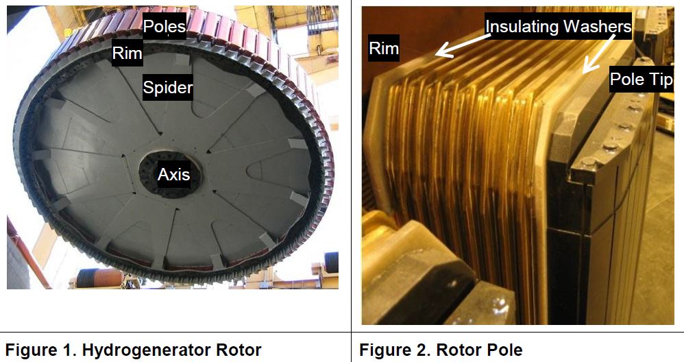
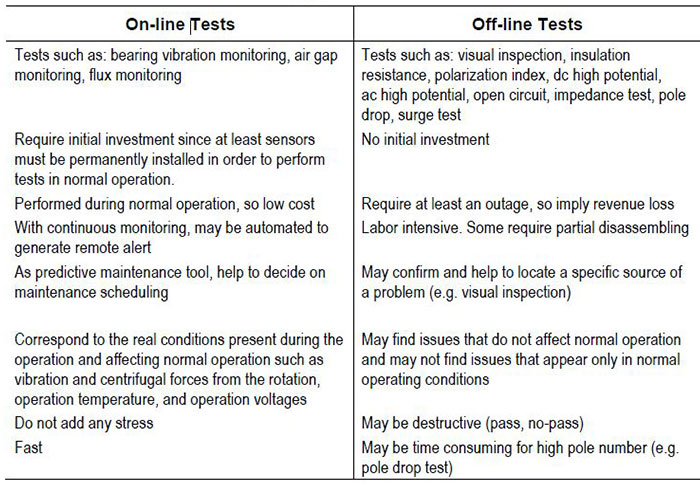
The pole pairs in the rotor periphery (Figure 1) act as fixed North and South magnets. The required Ampere-turns (AT) are produced by the dc excitation current circulating through the turns of the pole windings, connected in series. In large generators, the turns are made from strips of copper, either, rectangular pieces joined together, in the Picture Frame style (common in newer machines), or a continuous strip bent at the corners, in the Edge-Wise style. For both styles, in modern designs, the insulation between turns is usually made of Nomex™ strips bonded to the copper by a thermosetting resin, and the copper edges are exposed. The pole tip side of the winding has an insulating washer and the rim side of the winding may have either an insulating washer (Figure 2) or insulating blocks.
 The rotor winding insulation is exposed to stresses including:
- Thermal aging. The materials most susceptible to thermal degradation are organic bonding and backing materials, especially those in hot spots. The most common causes are: operating temperatures higher than design values due to overloading or high air temperatures; inadequate cooling due to poor design, manufacturing, or maintenance procedures; use of material with inadequate thermal properties; overexcitation for long periods; and circulating rotor currents caused by negative sequence stator currents during system voltage imbalance.
- Thermal cycling. Too-rapid or too-frequent load cycling for the design may cause
the cracking of the insulation bonding leading to increased looseness and abrasion. Windings may become distorted when restrained from returning to their cold position. - Pollution (tracking and moisture absorption). Exposed copper edges are most affected by conducting contaminants such as moisture (e.g. condensation), coal dust and oil dust mixtures, leading to turn failures and ground faults. Chemicals may attack the insulation.
- Abrasive particles. Cooling air with abrasive materials such as dust from brake pads may erode the insulation.
- Centrifugal force. This force at normal speed may tend to distort the coils and therefore crack their insulation. Both speed changes and inadvertent overspeed impose additional stresses to the insulation components.
- Repetitive voltage surges. Predominantly turn failures may be produced in weak insulation by transient voltages from system faults, faulty synchronization, asynchronous operation or static excitation spikes.
Rotor Winding Tests
Depending on when tests are performed, there are on-line and off-line tests available (Table 1)
Table 1. On-line vs. Off-line Tests [1]
New Flux Monitoring System
Flux monitoring is an on-line test for the rotor winding of synchronous machines
originally developed by GE over 40 years ago [1]. The test was intended for round rotor machines that have windings with coils distributed in pole slots (such as 2 or 4 pole turbogenerators). During normal machine operation, the flux from each passing pole induces a voltage e in a flux probe, here called conventional flux probe, or CFP.
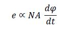 e= induced voltage
N= number of turns
A= average turn cross sectional area
dφ/dt = magnetic flux change rate
The CFP is fixed on a stator wedge, at the turbine end, at 10 or 2 o’clock position of the turbogenerator, avoiding magnetic segments of rotor wedges. The flux contribution of each coil is reflected as a peak in the induced voltage e when passing an individual pole slot. By symmetry, in absence of shorted turns, the absolute peaks of e, from corresponding slots in a pole pair, must be similar. A difference between those peaks will indicate shorted turns.
The conventional flux monitoring system has been enhanced to be used in hydrogenerators and other salient pole machines. The new system has a flux probe called TFProbe™ wired to a termination box, and an instrument called either RFAII™ in the portable version for periodic monitoring or FluxTracII™ in the permanent installed version for continuous monitoring.
Flux Probe
The new flux probe is glued on a stator core tooth to measure the main (total) flux form each rotor pole as it passes (Figure 3). One probe is required per machine.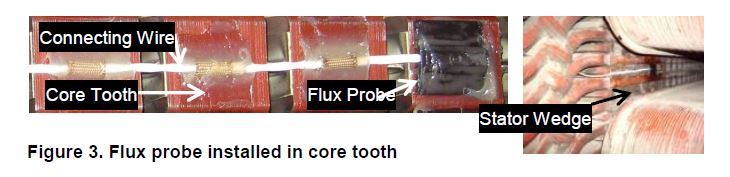
Some features of the probe include:
- Developed by the US Bureau of Reclamation [2,3]
- Coil is a printed circuit board with conductive turns on one side of a flexible material [3]
- Flat, thin, light probe. Suitable for small airgap size machines such as hydrogenerators
- Low profile presents minimal resistance to windage generated by rotating rotor
- Glued on a stator core tooth
- May be installed with rotor in place provided that spacing between poles is at least twice the stator slot pitch. Alternatively, a rotor pole may be removed
- It is used in conjunction with a sync sensor, a proximity switch that provides a once-per-revolution signal when it detects a target on the machine shaft (e.g. a small square with epoxy). The sync sensor is used to locate shorted poles, which is important in case of high number of poles. For motor-generators used in pumping stations, three targets may be used to get the type of operation (direction of rotation).
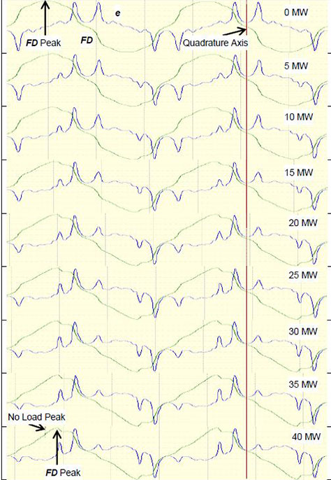
Figure 4. FD Pattern Changing With Load
Instrument
Both the portable instrument and the continuous monitor are based on a custom designed field programmable gate array allowing fast data acquisition at a very high sampling rate. The instrument integrates the induced voltage e to get back a signal proportional to the magnetic flux φ, and therefore proportional to the flux density (magnetic flux per unit area, or FD).
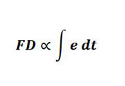 FD = flux density
e = flux probe signal (induced voltage)
When the load changes, the flux density pattern changes, as shown for a generator in Figure 4 (symmetrical signals without load become unsymmetrical
with load). Because the salient pole machine winding has only one coil per pole,
instead of the peaks of e (as done in round rotor machine analysis for individual
slots), the FD peak value for each pole is used for comparison, to find shorted
turns.
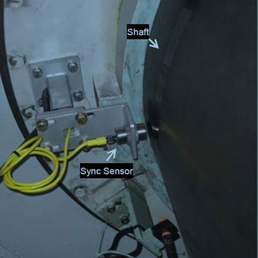
Figure 5. Sync Sensors
The instrument uses a Sync sensor (Figure 5), a proximity switch that provides a
once-per-revolution signal when it detects a target on the machine shaft. The
Sync sensor information allows fast location of the shorted poles relative to the
target. In case of motor-generators in pumping stations, the instrument may
recognize the operation mode by detecting the rotation direction with the Sync
sensor and three targets in the shaft (0º, 60º, and 180º).
The portable instrument covers most of the flux testing needs allowing manual
testing and stand-alone operation based on time, and upon selection, avoiding
saving tests with repeated FD pattern [4]. However, in some cases, additional
monitoring capabilities may be required such as alerts when shorted turns are
detected, remote communication for automation and supervision, data transfer
for third party on-line applications, access to test results at any moment, or
avoiding visits to plants due to safety or security concerns. For those cases, the
continuous monitor, permanently connected, is recommended.
Software
The software allows data downloading, displaying, and further analysis. In
addition to shorted turns, other factors affect the magnetic field from each pole,
such as: airgap size change, rotor out-of-round or off-centre, loose pole – key
migration, stator migration, and natural variations of pole’s physical position. The software allows calculation, and tabular and graph display of relative values of the FD peaks for further analysis with respect to the following values: average,
adjacent pole, and average with poles of the same sign. Figure 6 shows, for a
machine without shorted turns, two different comparisons: average and adjacent. The average graph shows clearly the eccentricity. In these plots the radial direction is proportional to flux density and the circumferential direction is the rotor pole number.
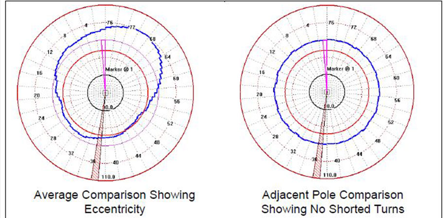
Figure 6. Comparison Algorithms
Figure 7 shows in an adjacent view, a shorted turn in pole 21 with its relative FD
peak beyond the limit value for alert.
Figure 7. Shorted Pole Detected in Pole 21
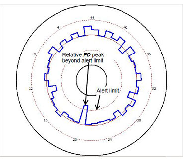
Figure 7. Shorted Pole Detected in Pole 21
Conclusion
Flux monitoring has proven to be a suitable tool for rotor shorted turn detection in synchronous machines. The on-line tests of rotor windings, including flux monitoring, are an attractive solution for hydrogenerator rotor testing. However, due to the small airgap size and rotor construction, hydrogenerators and salient pole machines in general require different flux probes and different analyzing algorithms.
The new flux monitoring system detects shorted turns in hydrogenerators while being immune to false indications caused by air gap problems.
References
1. G.C. Stone, A. Boulter, I. Culbert, H. Dhirani, “Electrical Insulation for Rotating Machines”, IEEE Press-Wiley, Jan. 2004.
2. Jan Stein, “Field Testing of Continuous Hydrogenerator Air-Gap Flux Monitor: Feasibility Study” (1011282), 2004
3. US Patent No. 6466009, Flexible Printed Circuit Magnetic Flux Probe, issued October 15th, 2002
4. On-line Hydrogenerator Rotor Winding Condition Assessment Using Flux Monitoring S.R. Campbell, G.C. Stone, M. Krikorian, G. Proulx, Jan Stein
Authors
Mladen Sasic is a Rotating Machines Specialist with Iris Power, Canada. Prior to joining Iris, Mladen was with ADWEL International LTD., where he was involved in design and application of test equipment for on-line and off-line testing of rotating machines. Mladen Sasic received a B.S. degree in Electrical Engineering from Sarajevo University, Yugoslavia in 1987. He is a senior member of the IEEE and is a registered professional engineer in Ontario, Canada.
Greg Stone is a Dielectrics Engineer with a PhD in Electrical Engineering from the
University of Waterloo, Canada. For 17 years he was a rotating machine test engineer with Ontario Hydro. Since 1990, he has been with Iris Power, a manufacturer of diagnostic test equipment. He is a Past President of the IEEE Dielectrics and Electrical Insulation Society and Fellow of the IEEE and the Engineering Institute of Canada.
Pablo Rojas, graduated as an Electrical Engineer from the Universidad Nacional de Colombia, and is a registered professional engineer in Ontario, Canada. He has worked for SIEMENS and ABB, and currently works for Iris Power as a technical specialist on rotor winding problems.
Presented at HydroVision Brazil Sept 2011