
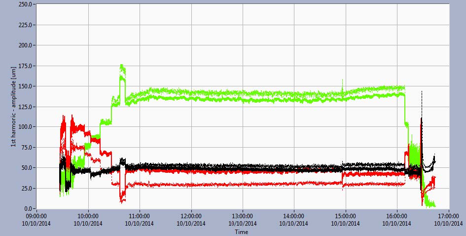
Figure 3 Trend diagrams of amplitude changes (upper diagram) and phases (middle diagram) of the first harmonic of relative vibrations on UGB, LGB and TGB. Amplitudes of vibrational velocity of bearing housing (lower diagram) in directions X and Y during the experiment.