Abstract
Flux monitoring via permanently installed air gap flux probes is a proven technology used for many years in synchronous machines to determine the presence of turn-to-turn shorts in a rotor winding. This information is critical in planning maintenance and in vibration analysis. Traditionally, flux measurements have been done using flux probes installed on a stator wedge connected to portable or permanently installed instruments. To achieve a reliable diagnostic, the signals from the flux probe had to be measured under different load conditions ranging from no load to full load. This requirement presented a serious obstacle in application of this method on base load units. A new design of flux probe installed on a stator tooth, and novel algorithms used to analyze measurements can help minimize the need for tests at different load conditions and still provide reliable diagnostics. This paper describes the new method and its advantages.
Causes and effects of shorted turns in rotor windings
A turbine generator rotor usually consists of a solid forging made from magnetic alloy steel and copper windings, assembled in slots machined in the forging. The winding is secured in slots by steel, bronze or aluminum wedges. At each end of the rotor, end sections of the rotor winding are supported by retaining rings. Modern rotor winding insulations are made mostly from epoxy/polyester glass/Nomex™ laminate strips and channels. The strips are used to provide inter-turn insulation and molded channels are used to provide ground insulation. The rotor insulation should be designed to withstand electrical, mechanical, thermal and environmental stresses. Shorted turns are usually the result of failed insulation between rotor turns and are a common occurrence in large turbine generators. Major causes of shorted turns in rotor windings are contamination with conductive debris and turn-to-turn movement of the rotor windings caused by high centrifugal loads and axial thermal expansion forces. The condition of the rotor winding insulation is difficult to assess during a shutdown due to limited access and the frequently intermittent nature of faults at operational speed and at standstill. Consequently, on-line testing is a more effective way to detect shorted turns.
Flux monitoring using temporary or permanently installed flux probes has been used since the early 1970’s [1]. Flux measurements are used to determine existence of turn-to-turn shorts in the rotor winding. To date, all of the methods available were based on measurement of relatively weak stray flux (rotor slot leakage flux) using flexible or non-flexible polymer encased stator wedge mounted probes [2-4]. The stray flux is proportional to the total ampere-turns in each rotor slot. If shorts develop between turns in any slot, then the ampere turns in that slot drop, and stray flux across that slot is reduced. The magnitudes of these stray fluxes can be measured using portable or permanently installed instrument and shorted turns can be identified by comparing the difference in the induced voltages from pole to pole. The main challenge in existing technology is the need to maneuver the generating unit load to achieve the maximum sensitivity to shorted turns in every slot of a rotor. This is particularly challenging in detection of shorted turns on coils 1 and 2, installed close to the
pole face. To assess condition of coils 1 and 2, using existing technology, the generator needs to produce maximum active load and maximum negative reactive load. Since this mode of operation is frequently not possible, many suppliers of existing technology do not provide reliable assessment of the condition of coil 1.
Relationship between shorted turns and vibration
Different factors will affect how serious problems caused by shorted turns will be. In many cases the rotor will still run without significant consequences. However, the most noticeable effect can be increased rotor vibration. Since the resistance of coils with shorted turns is lower, they are likely to operate at lower temperatures compared to coils without shorted turns. This temperature difference will cause uneven heating of the rotor forging and can cause the rotor to bow. The bowing will increase with increasing load due to higher temperatures resulting from higher excitation current. Therefore, this situation is frequently described as thermally sensitive vibration. Two pole rotors are much more sensitive to thermal vibrations than four pole rotors.

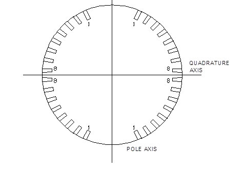
Figure 1. Cross-section of a two pole rotor
The main reason for thermal bowing of a rotor is its asymmetrical design. A rotor forging is made of magnetic steel and designed to carry the flux produced by the rotor winding. A rotor EPRI 11th Steam Turbine Generator Workshop, Milwaukee, WI, USA, August 2009 body consists of a pole face area and winding slots machined axially. Pole face areas, see Figure 1, are cut in half by the Pole axis. The coil closest to the pole face is coil 1. Coils with higher numbers, usually 7-9 on two pole rotors, are located closest to the Quadrature Axis. The bowing of the rotor and magnitude of vibrations will depend on the design of the rotor, number of shorted turns and the location of coils with shorted turns [6]. Generally, shorted turns in coils 1 and 2, closest to the pole face produce higher magnitude vibrations compared to shorted turns in coils closer to Quadrature axis. The reason for this is that shorts in lower coil numbers produce less elongation in the axial direction of pole face compared to higher numbered coils due to lower temperature at pole face. Coils without shorted turns are running at higher temperature and thus greater elongation compared to coils with shorted turns. Consequently, the bowing will increase with increased rotor current, and may limit MW output due to excessive vibration. Thermal vibration is directly linked to changes in rotor current, with reduction of rotor current, vibrations will go down and vice versa. The degree of thermal sensitivity is determined by measurement of vibration at different loads. In cases where vibrations are higher than or very close to the operational limits, trim balancing of the rotor is usually the first step taken to alleviate the problem. This operation does not require removal of the rotor but does not fix the origin of the problem, shorted turns in rotor winding. If successful, trim balancing can reduce the vibration at full load and enable the generator to be operated within safe vibration limits. However, trim balancing weights placed on the rotor to minimize vibration at full load will introduce vibration at lower loads (lower temperatures), when rotor bowing is not significant. The best way to determine whether rotor shorted turns are the cause of rotor vibration is to analyze both on-line vibration monitoring and on-line air gap flux monitoring results.
New Flux Measuring Hardware and Software
On-line measurements require the permanent installation of a flux probe on the stator to measure the slot leakage flux. A unique flux probe called a Total Flux Probe™ has been developed for this application [5]. The TF Probe™, is a small, thin flexible, printed circuit board transducer which can be affixed to a tooth of the stator. The TF Probe measures the total air gap flux, and is easy to install, requiring no invasive drilling of stator wedges. In certain cased it can be installed with the rotor still in place.
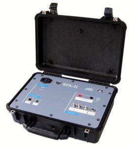
New portable instrument and interpretation software have been developed and are available in two different options, for salient pole and non-salient pole rotors. The new instrument is equipped with inputs for different types of flux probes and three different synchronization methods are possible: using a dedicated synchronization shaft-mounted marker, internally to AC power frequency, or externally to any other signal in 40-240 VAC range. The instrument is based on a custom designed FPGA circuit capable of fast data acquisition at a very high sampling rate. This sampling rate enabled the use of new algorithms for detection of shorted turns. Different communication protocols (USB, LAN) can be used for connecting the instrument to a PC. Data acquisition without a PC is also possible, if test parameters and measurement intervals are previously defined. Two stand-alone data acquisition modes are available, time and load based. Time based can be used to collect data in user specified time intervals, as short as one measurement every five seconds. This method is very useful to collect different load data automatically at different loads during fast load changes.

Figure 2. Portable Rotor Flux Analyzer
All measurements collected are stored in the instrument internal memory and can be downloaded to a Microsoft Access™ data base, consisting of a number of folders representing stations and machines tested. Unlike with traditionally techniques, measurements with the new instrument do not have to be performed at different generator loading points to achieve maximum sensitivity to shorted turns.
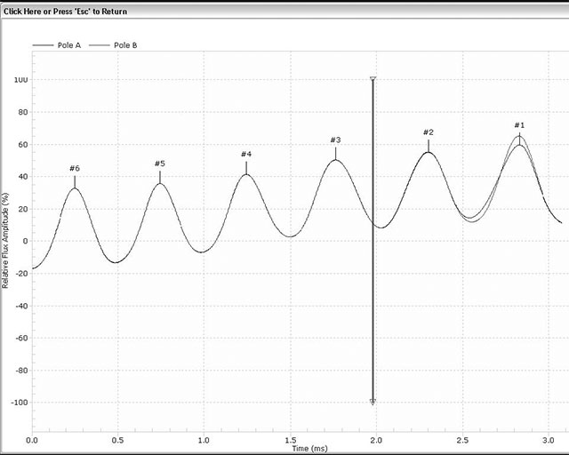
A typical two pole rotor measurement result is shown in Figure 3. The grey line indicates the measured signal and the green line is the integrated value of the measured signal. Each peak of the grey line marked with blue or red numbers indicates a leading coil of pole A or pole B. In the absence of shorted turns, corresponding peaks of two poles should be the same amplitude. To determine the condition of inter-turn insulation in each coil, traditional methods required multiple measurements at different loads. In this case, the position of maximum sensitivity is indicated by the vertical green line in Figure 3, described as Flux Density Zero Crossing (FDZC). With the generator at zero load, the FDZC will be positioned at the Quadrature axis (between highest numbered coils of pole A and pole B). As the generator load is increased, FDZC will move toward lower numbered coils, but typically will never reach coil number 1.

Figure 3. Typical two pole rotor flux measurement
Case Study
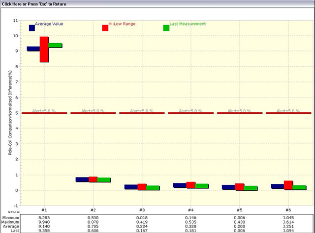
A 100 MVA generator was equipped with Total Flux probe during a scheduled shut-down. Although the generator had increased vibration for a number of years, the cause was not known and repairs were not attempted during this shut-down. A few months later, the first flux measurements were made at maximum loading, see Figure 4. Comparison of pole A to pole B leading slots, indicated a difference in amplitude close to 9% in coil number 1. Although flux measurements could not be made at different loads, vibration monitoring has confirmed thermal dependence of vibration amplitudes.

Figure 4. Leading slots normalized peaks, pole A to pole B comparison
Figure 5. indicates a summary of multiple measurements at slightly different loads, for each coil. Coil 1 normalized pole to pole amplitude difference ranged from 8.2% to 9.9%, while all other coils had difference lower than 1%.

Figure 5. Summary of multiple readings, for each coil
Conclusion
An improved system for detection of shorted turns on rotor coils has been developed. The system consists of an easily installed probe that measures the main flux in the air gap, and a portable Analyzer instrument, with new algorithms for rotor short detection. As a result of these improvements, the overall system sensitivity to shorted turns has been greatly improved from conventional techniques. This new system can detect the presence of shorted turns without the need to obtain measurements at various load conditions.
References:
[1] Albright, D. R. “Interturn Short-circuit Detector for Turbine-Generator Rotor Windings”, IEEE Transactions on Power Apparatus and Systems, Vol. PAS-90 Number 2, March/April 1971
[2] Donald R. Albright, David J. Albright and James D. Albright “Generator Fields Winding Shorted Turn Detection Technology” IRMC, May 1999
[3] M.P. Jenkins, D.J. Wallis “Rotor Shorted Turns: Description and Utility Evaluation of a Continuous On-line Monitor”, EPRI Predictive Maintenance and Refurbishment Conference, December 1993
[4] Alan Whittle “Continuous Rotor Flux Monitoring”, 10th EPRI Generator Workshop, August 2007
[5] US Patent No. 6466009, Flexible Printed Circuit Magnetic Flux Probe, issued October 15th, 2002
[6] G. Klempner, “Rotor Shorted Turns-Detection and Diagnostics”, EPRI Generator Predictive Maintenance and Refurbishment Conference, December 2003

