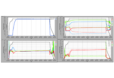
Iris Power | Rotor and Stator Geometry Analysis Using Air Gap Figure 5. Vibration signals recorded during the run
Iris Power | Rotor and Stator Geometry Analysis Using Air Gap Figure 5. Vibration signals recorded during the run

Iris Power | Rotor and Stator Geometry Analysis Using Air Gap Figure 5. Vibration signals recorded during the run
Iris Power | Rotor and Stator Geometry Analysis Using Air Gap Figure 5. Vibration signals recorded during the run