
Abstract – The rotor windings of synchronous motors and generators are usually very reliable. However, the turn insulation in such machines will eventually degrade and puncture due to thermal aging, load cycling and/or contamination. Although turn shorts do not directly lead to machine failure, they can lead to high bearing vibration, may damage synchronizing systems within brushless motors and may limit output. Off-line tests are available to detect rotor winding shorted turns, however they may be unreliable since the rotor is not spinning for the test and if only a few shorts are present, the shorts may disappear once the rotor is spinning (or vice versa). With funding from the US Electric Power Research Institute, a new type of on-line magnetic flux test has been developed that is suitable for salient pole machines, and in particular the salient pole rotors in 4 (or more) pole hydrogenerators and synchronous compressor motors that are widely used for air separation. The test requires retrofitting a small magnetic flux probe to the stator core and instrumentation to interpret the small voltage signals that are measured from the probe.
Index Terms – salient pole, rotor winding, motor, shorted turns, turn insulation.
I. INTRODUCTION
Most of the synchronous motors used in the air separation business have salient pole rotor windings having 4 to 26 poles. Each field pole is an electromagnet, and the rotor winding is made by mounting the poles in pairs on the rotor rim. The poles are then electrically connected to the DC supply (normally up to a few hundred volts) in such a way as to create alternating north and south poles around the rim. Each field pole consists of laminated steel core, which looks rectangular when viewed from the rotor axis. Around the periphery of each pole core are the copper windings. Fig. 1 is a photo of a rotor from a 20-pole salient pole synchronous motor.
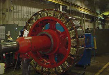
Fig. 1 Rotor from a salient pole synchronous motor
There are two basic types of salient pole designs [1]. The older type of field pole design, and still the design used on motors less than a 1000 HP or so, is called the multi-layer wire wound type. In this design, magnet wire is wrapped around the pole (Fig. 2). The magnet wire usually has a rectangular cross section, and many hundreds of turns are wound on the pole, several magnet wire layers deep. The turn insulation is the magnet wire insulation. Looking from the axial direction, the laminations are shaped to have a pole tip (which is the part of the rotor pole which is closest to the stator) to support the winding against the centrifugal force. Insulating washers and strips are placed between the magnet wire and the laminations to act as the ground insulation.
For larger machines, the ‘strip-on-edge’ design is favored since it can be made to better withstand rotational forces. In this case a thin copper strip is formed into a ‘picture frame’ shape, so that the ‘frame’ can be slid over the pole laminations (Fig. 3). Laminated insulating separators (made from epoxy glass laminates or NomexTM materials) act as turn insulation to insulate each copper ‘frame’ from one another. On some copper ‘frames’, especially those near the pole face, an insulating tape may be applied to the copper strip to increase the creepage distance. The tape and separators form the turn insulation, and the copper ‘picture frames’ are connected in series to make the coil. As with the multi-layer design, the winding is isolated from the grounded pole body by insulating washers and strips (Fig. 3). Often the entire pole may be dipped in an insulating liquid to bond the various components together.
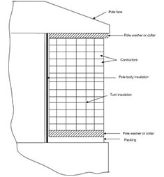
Fig. 2 Multi-layer wire wound design
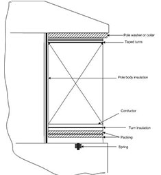
Fig. 3 Copper “strip on edge” salient pole design
As described later, thermal and mechanical stresses gradually age the turn and ground insulation. In addition, partly conductive contamination on the rotor poles may also degrade the insulation. If a ground fault occurs, ground fault detectors will normally automatically shut down the machine. More commonly, it is the turn insulation that degrades and fails first. This shorts some of the copper turns together but does not result in a failure of the machine. Instead the magnetic field from that rotor pole will be diminished. Since the magnetic field from one pole is weaker than the other poles, this will lead to an asymmetric magnetic force across the air gap, and thus higher bearing vibration at a frequency corresponding to once per revolution. The fewer the number of poles on the rotor the more serious may be the vibration from this unbalanced magnetic pull. More usually, one or more shorted turns just cause higher bearing vibration that in many cases may be tolerable. However, if more and more turn shorts occur over time, high vibration may force a shutdown of the motor. In addition, for motors with brushless exciters, the shorted turns may also lead to failure of the components within the motor intended to synchronize the motor to the power system. Thus, although shorted turns on the rotor do not automatically lead to a motor failure, they are an indication of a problem that may cause problems in the future.
This paper describes the aging processes of salient pole turn insulation, and briefly presents the off-line method that has been used to detect turn shorts. The development of a new on-line test based on the measurement of the main magnetic flux from the rotor is described. This on-line test permits the trending over time of the number of shorted turns occurring without the need of a shutdown, enabling better prediction of when maintenance is needed. Results of the new flux test on both hydrogenerators and motors are then presented.
II. ROTOR INSULATION DETERIORATION PROCESSES
Rotor winding insulation deteriorates over time due to thermal aging, thermal (or load) cycling, contamination of the insulation, abrasion of the insulation due to particles in the airgap, and of course the high mechanical force caused by high speed rotation.
A. Thermal Deterioration
Modern salient pole winding designs use Nomex™ ground and turn insulation in strip-on-edge windings; DacronTM glass covered high temperature enamel turn insulation in wire wound poles; and thermosetting bonding resins to provide an insulation system that has a thermal rating of at least Class F (155°C). If these materials are operated at Class B (130°C) temperatures, they should have a thermal life of 30 years or more. However, operation above about 130°C will shorten the life of the insulation. The materials most susceptible to thermal degradation are organic bonding and backing materials (epoxy resins and polyester films), and the hotter the temperature and the longer the time at high temperature, then the more brittle the insulation becomes and the more susceptible it becomes to mechanical force which will crack the insulation.
The thermal life of insulation at hot spots in windings is significantly reduced if the margin between operating temperature and thermal rating is significantly reduced. This effect is more critical in older Class B insulation systems and the presence of such hot spots is very difficult to detect.
The following are the most common causes of thermal aging in salient pole windings:
1. overloading leading to operating temperatures well above expected design values,
2. high cooling medium temperatures or inadequate cooling which can be general, e.g., insufficient cooling air or cooling water, or local dead spots in the cooling circuit due to poor design (especially at the blocking between poles), manufacturing or maintenance procedures,
3. the use of materials that have inadequate thermal properties and consequently deteriorate at an unacceptable rate when operated within design temperature limits,
4. over excitation of rotor windings for long periods of time, and
5. negative sequence currents in rotor windings due to system voltage unbalance, etc.
B. On-Off Cycling
There are two heat sources when a synchronous motor is started. One mainly applies to motors that are started direct-on-line, causing heating due to currents flowing in the pole tips of solid pole rotors, or the damper winding in those with laminated poles. The other is heat generated by the current in the windings once excitation is applied.
Frequent starts and stops cause copper expansion and contraction as the copper temperature increases or decreases. Relative movement due to the different coefficients of thermal expansion in the various components leads to relative movement between the copper and the turn insulation and consequent abrasion.
The thermal cycling resulting from frequent starts and stops leads to the cracking of the resin or varnish bonding the insulation system components together. This causes loosening and relative movement between these components which leads to increased looseness and abrasion. Also, if the windings are restrained from returning to their cold position they may become distorted from this process. Poor design or too-rapid or too-frequent load cycles for the design are the root causes. Clearly the more motor starts there are the more likely this is to be a problem. In addition, motors designed for few starts, but actually exposed to much more frequent starting due to operational or power system conditions, are more likely to suffer from this problem.
C. Contamination
A likely cause of rotor winding shorts in air separation applications is contamination. The strip-on-edge type is most susceptible to failure from contamination by partly conducting materials. Such problems are not confined to machines with open type enclosures since oil leaking from bearings and moisture from condensation, combined with particulates, can contaminate windings. The contamination has a tendency to accumulate near the blocking between poles. Such problems are less likely in wire wound types due to encapsulating the windings to keep contaminants out.
When contaminants such as moisture, soot, dust, oil and dust mixtures cover the surfaces of salient pole windings they can produce conducting paths between turns and to ground. This can lead to turn-to-turn failures (especially in strip-on-edge types) and ground faults due to electrical tracking. Certain chemicals can also attack insulating materials to cause them to degrade.
Earlier insulation systems containing materials such as asbestos, cotton fibers, paper etc. bonded by organic varnishes are much more susceptible to failure from moisture absorption.
D. Abrasive Material Attack
Abrasive dust from the surrounding atmosphere carried into the interior of a motor by cooling air will abrade the rotor winding insulation surfaces. This may eventually expose the conductors in multilayer wire wound poles resulting in turn shorts. Also the ground insulation in both types of salient pole windings and their interconnections may be eroded to cause ground faults. The use of open enclosure machines without inlet air filters in locations where there are abrasive materials in the environment can lead to this problem.
E. Centrifugal Forces
One of the most common causes of failure in salient pole rotor windings are the continuous centrifugal forces imposed on them by rotation and the cyclic centrifugal forces induced by starting and stopping.
The centrifugal forces imposed on rotor winding insulation system components tend to distort the coil conductors and crack the coil insulation if they are not adequately braced, or the insulation has weakened as a result of thermal aging or on-off cycling. If the pole winding bracing is inadequate or becomes loose, the resulting coil vibration and movement of the coils on the poles will cause abrasion of the conductor and ground insulation. Inadequate inter-pole bracing in large, high-speed machines, will lead to coil distortion while erosion from loose windings will occur mainly during starts and stops. Winding looseness can also lead to pole washer and inter-coil connection cracking from fatigue. Mechanical winding stresses will become excessive and cause serious winding damage if the rotor is operated at over speed.
III. OFF-LINE DETECTION OF SHORTED TURNS
The most common way to detect shorted turns (and incipient ground faults) is to perform a ‘pole drop’ test [1]. In the pole drop test, an AC voltage, for example 120 V ac, is applied between the positive and negative slip rings when the motor is shut down. The voltage across each pole is then measured. If shorted turns are present, there will be a smaller than average voltage drop across that pole. This test has three significant disadvantages:
1. it can only be performed with the motor shut down,
2. it is time consuming to perform, especially on a large rotor with many poles, and
3. since the rotor is not rotating, the centrifugal forces are not occurring, and thus some shorts may not be present in the pole drop test, which nevertheless will be present at normal rotating speeds. Conversely, shorts may occur when the machine is shut down that are not present when the rotor is spinning.
Finally, motors used for air separation often only see planned shutdowns every 5 years or so. Yet shorted turns can occur and multiply to the point of very high bearing vibration in only a few years. Thus a test done 3 or 4 years ago may not give a good indication of the condition of the turn insulation at the present time. Only an on-line test can do this. In addition, discovering turns shorts by a pole drop test only when the motor is shutdown during a turnaround, often means that the plant turnaround must be extended to accommodate the time to refurbish the defective poles.
IV. PRINCIPLES OF MAGNETIC FLUX MONITORING
A. Airgap Magnetic Flux
Companies are trying to minimize the work (such as pole drop tests) performed during unit shutdowns due to restricted resources. In addition, many companies are moving to predictive maintenance to plan any repair work based on on-line condition monitoring. Thus, there is a need for an on-line tool that can replace the pole-drop test. For the past 30 years, electric power utilities have been implementing magnetic flux monitoring in the air gap between the rotor and stator to detect shorted turns on the cylindrical rotors of high speed steam-turbine generators [1, 2, 3]. This technology has rarely been applied to salient pole windings, possibly because the salient pole rotors are very different from cylindrical pole rotors and interpretation of the flux patterns is not obvious. In 2003, EPRI and the New York Power Authority initiated a research project to determine if a variant of flux monitoring could be applied to salient pole rotors, so that an online monitor could produce a reliable indication of rotor shorted turns [4].
Rotor flux monitoring involves measuring the magnetic flux in the generator or motor air-gap to determine if field winding shorts have occurred in the rotor poles. The radial magnetic flux from the rotor is detected by means of a coil or “probe” consisting of several dozen turns that is glued to a stator core tooth (Fig. 4). As each rotor pole sweeps by the flux probe, a voltage is induced in the coil that is proportional to the flux from the pole that is passing the coil. The voltage is measured by electronic instruments. In a salient pole machine, the radial magnetic flux profile across each rotor pole depends on the MW and MVAr loading of the machine. After corrections for variations in the air-gap, any change in the flux profile within a pole at a given load must be due to shorted turns.
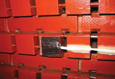
Fig. 4 Flux Probe (black) mounted on a stator core tooth, with connecting lead (white)
As each pole in the rotor passes the coil, there will be a peak in the induced voltage caused by the magnetic flux from the pole. The voltage can then be recorded and each peak of the waveform represents the “average” flux across one rotor pole. Any turn short in a pole reduces the effective ampere-turns of that pole and thus the signal from the flux probe associated with that pole. The recorded waveform data can then be analyzed to locate the poles containing the fault, as long as one has calibrated the pole location from a ‘start’ location marked on the rotor shaft.
An algorithm was developed to maximize the sensitivity to a pole with shorted turns. The algorithm involves integrating the data from each pole, applying autocorrelation, and comparing the integral from each pole to an opposite polarity pole.
B. Flux Probe Design
Flux probes used in synchronous high speed machines are usually designed in the shape of a cylinder and installed in the air gap between stator and rotor. Since the air gap in salient pole motors is much smaller and construction of rotor is different, flux probes used in high speed turbine generators could not be used in hydrogenerators and motors.
A new type of probe [5] has been designed to overcome disadvantages of existing designs. The new probe is comprised of a number of printed circuit layers, printed on a flexible base material. The flexible probe is designed for application on a stator tooth. The very low profile of the installed probe enables its use on machines with small air gaps. In salient pole machines, it can generally be installed with the rotor still in place, using a Class F epoxy glue.
C. Portable Flux Monitoring Instrument and Software
The signals from the flux probe cannot directly indicate shorted turns since other factors can affect the flux, such as the distance between the pole and the stator. Thus, a new portable instrument was developed which digitizes the voltage signal from the flux probe with high resolution. Besides an input for the flux probe, the device also has an input for a shaft synchronization sensor (or “key phasor”), which enables any field pole with a short to be identified. The instrument has a custom designed field programmable gate array and is capable of fast data acquisition at a very high sampling rate. This sampling rate enabled the use of new algorithms for detection of shorted turns, even if the air gap is changing due to rotor imbalance, stator core movement, etc.
V. TEST RESULTS
A. Hydrogenerator Tests
The initial experiments with the flux monitoring system were carried out on many dozens of hydrogenerators which generally have a large number of salient poles. An example is shown below. The voltage waveform from a flux probe is shown in Fig. 5. The generator was operated at no load conditions, 0 MW and 0 MVAr, resulting in a symmetrical shape of both the raw signal measured (blue line) and integrated values of raw voltage signal (red line). Since the shape of the signal changes at different loads of the machine (Fig.6), raw data should be integrated for further processing.
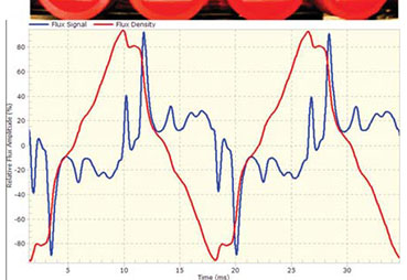
Fig.5 Shape of the flux signal at 0 MW, 0 MVAr. The vertical scale is the voltage output of the flux probe while the horizontal axis is the circumferential position around the rotor.
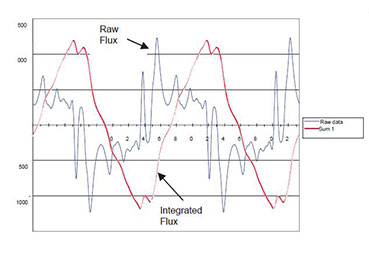
Fig. 6 Shape of the signal at 125 MW, 0 MVAr
Given that change in the flux profile within a pole at a steady load must be due to shorted turns, comparison of one pole to another can be used as an indication of shorted turns. The transformed flux data can then be shown as a polar plot (Fig. 7). Minor differences between poles and rotor or stator eccentricity will result in a less than perfect circle.
Fig. 8 is the result from the same 64 pole rotor with temporarily applied shorts on poles 8 and 48. The poles with shorted turns are clearly determined by the lower flux magnitude at these poles.
In many of the tests on hydrogenerators, the pole drop test did not find the shorts found with the on-line flux measurement, and vice versa. Only after installations on many dozens of hydrogenerators did we become convinced that the cause of the bad correlations with the pole drop test was that the pole drop test itself was not a good indicator of what shorts were present in service. Presumably, shorts that are present when the rotor is rotating may clear when it is shut down, and vice versa.
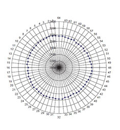
Fig. 7 Polar flux diagram of a hydrogenerator operating at full power. The machine has 64 poles and no known shorts.
The radial scale is the accentuated average flux and the circumferential scale is the rotor pole number.
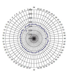
Fig. 8 Polar diagram of 64 pole rotor with shorts detected at poles 8 and 48
B. Motor Test Results
In 2004 flux probes were installed on seven stator cores of salient pole motors used to drive compressors for air separation processes. These motors had from 6 to 22 poles. Figs. 9 and 10 show the resultant flux plot from a 22 pole motor with a strip-on-edge rotor pole design. Figs. 11 and 12 show the flux data from a 6-pole motor. There are minor differences in the magnetic flux from each pole caused by different pole mounting (and thus slightly different air gaps). However, none of the poles has a significant enough reduction in flux to indicate that shorted turns on a pole are indicated. Figures 9 to 12 also indicate the flux measurements are repeatable over time. These machines do not have increased bearing vibration, which supports the belief that there are no shorted turns. To date, none of the motors monitored shows evidence of shorted turns.
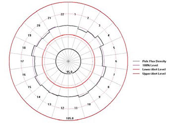
Fig. 9 Flux plot recorded in 2006 from a 22 pole motor

Fig. 10 Flux plot recorded in 2011 from the same motor as Fig. 9
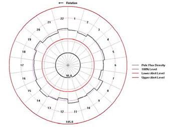
Fig. 11 Polar plot recorded in 2007 of flux from a 6 pole motor.
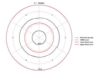
Fig. 12 Polar plot recorded in 2011 of the same motor as Fig. 11
VI. CONCLUSIONS
Gradual aging of the turn insulation in salient pole rotor windings can eventually lead to shorted turns. These shorted turns may create high vibration of the rotor and in severe cases where there are few poles and a number of shorted turns, the probability of a motor shutdown due to high vibration increases.
The most widely applied method for detecting shorted turns in the rotor is the pole drop test. Since the test is done with the rotor not spinning, the test may not find all the shorts that can occur in service. Also, the pole drop test is usually performed infrequently, and thus the need for rotor refurbishment is often a surprise which can extend the turnaround duration.
Research has lead to a new on-line test that can detect the shorted turns during normal service, by measuring the magnetic flux from each rotor pole using a stator based magnetic flux sensor. Initial results with the new technology are presented.
VII. REFERENCES
[1] G. C. Stone et al, Electrical Insulation for Rotating Machines, IEEE Press-Wiley. 2004.
[2] D. R. Albright, “Interturn Short-circuit Detector for Turbine-Generator Rotor Windings”, IEEE Transactions on Power Apparatus and Systems, vol PAS-90 Number 2, pp 478-483, March/April 1971.
[3] S.R. Campbell, J. Kapler, M. Sasic, G.C. Stone, “Detection of Rotor Winding Shorted Turns in Turbine Generators and Hydrogenerators”, CIGRE Paper A1-206, August 2010.
[4] S.R. Campbell, “Instrument Development for Continuous Flux Monitoring in Hydrogenerators”, EPRI Report 1016148, 2008.
[5] US Bureau of Reclamation, US Patent No. 6,466,009 B1, “Flexible Printed Circuit Magnetic Flux Probe” issued 15 October 2002.
VIII. VITAE
Mladen Sasic is a Rotating Machines Specialist with Iris Power, Canada. Prior to joining Iris, Mladen was with ADWEL International LTD., where he was involved in design and application of test equipment for on-line and off-line testing of rotating machines. Mladen Sasic received a B.S. degree in Electrical Engineering from Sarajevo University, Yugoslavia in 1987. He is a senior member of the IEEE and is a registered professional engineer in Ontario, Canada.
Jan Stein is a Senior Project Manager at EPRI. Jan has 25 years experience in R&D, application and design of large motors and generators. Prior to joining EPRI in 1985, he worked at Siemens-Allis in Milwaukee, WI, and Siemens/KWU in Germany. He has co-authored many papers.
Chris Stinson is Team Leader for Reliability – Americas, with Air Liquide and holds a Bachelor of Science in electrical and computer engineering from Clarkson University in Potsdam, NY. Upon graduating in 1989 he worked for General Electric Company’s Apparatus Service Division. There he focused on the repairing and maintaining of customers’ electrical equipment. He joined Air Liquide America in 1998 as an electrical engineer for maintenance where he helped integrate electrical work activities for the Reliability Centers. In 2004 he was recognized as a group expert for electrical and again in 2008 as a group senior expert with Air Liquide.
Greg Stone is a Dielectrics Engineer with a PhD in Electrical Engineering from the University of Waterloo, Canada. For 17 years he was a rotating machine test engineer with Ontario Hydro. Since 1990, he has been with Iris Power, a manufacturer of diagnostic test equipment. He is a Past President of the IEEE Dielectrics and Electrical Insulation Society and Fellow of the IEEE and the Engineering Institute of Canada.